 Comprehensive test and measurement service provider-Shenzhen Weike Electronic Technology Co.
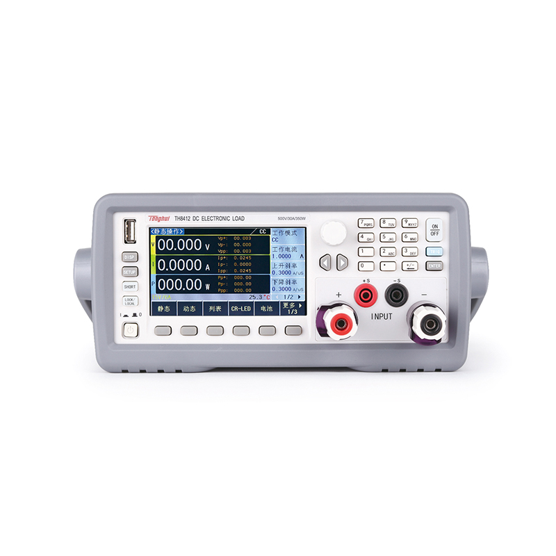


TH8400 series is a high-precision, high-intelligence, easy-to-operate DC electronic load. This series of instruments collects a variety of test functions, superior performance, and the use of LCD screen display, display clear, operation menuization, fast and convenient, can be well adapted to the production site rapid operation needs and laboratory high accuracy and high stability needs.
The TH8400 series programmable DC electronic loads include the following types:
| model number | input voltage | amps | power (output) |
| TH8401 | 150V | 30A | 175W |
| TH8402A | 150V | 30A | 350W |
| TH8402 | 150V | 60A | 350W |
| TH8403 | 150V | 120A | 1000W |
| TH8404 | 150V | 180A | 1500W |
| TH8405 | 150V | 240A | 2000W |
| TH8411 | 500V | 15A | 175W |
| TH8412 | 500V | 30A | 350W |
Functional Features
Conventional mode (4 types)
CC Constant current mode
An electronic load always draws a constant current, regardless of whether the voltage changes.

CR Constant Resistance Mode
An electronic load is equivalent to a constant resistance, and the load changes current linearly with voltage.

CV Constant Voltage Mode
The electronic load controls the voltage output from the power supply by adjusting the pull current according to the set voltage value.

CP Constant Power Mode
An electronic load is equivalent to a constant resistance, and the load changes current linearly with voltage.

Advanced modes (12)
DYN Dynamic Load Mode
A dynamic test frequency of up to 25kHz can be used to test the dynamic characteristics of a power supply over a wide bandwidth, with two current levels that can be set, the duration of each of the two current levels, the rising slope, the falling slope, and the number of repetitions. This function can be used to test the instantaneous high current tolerance of D/D converters and batteries.


SWP Dynamic Frequency Sweep Mode
The electronic load provides a programmable dynamic frequency sweep to invert the frequency to find the worst case voltage of the object to be measured. Dynamic Frequency Sweep requires the setting of two current levels, start frequency, end frequency, step frequency, duration, rise slope, and fall slope. During operation, the electronic load will pull current at the set frequency for the set duration. Frequencies up to 25kHz are used to capture the worst case Vp+, Vp- and corresponding Fp+, Fp- of the power supply under test.

CR-LED Analog LED Test Mode
By setting the on-state voltage and resistance of the light-emitting diode, it can realistically simulate the actual load characteristics of the LED, avoiding the oscillations generated by the unstable voltage and current under the conventional constant resistance mode (CR), and thus detecting the real load conditions of the LED power supply.

BATT Battery Test Mode
Load test battery performance, discharge conditions support CC, CR and CP three ways, by setting voltage, time, current capacity or power capacity of four conditions to let the electronic load to stop pulling load, to ensure that the battery will not be over-discharged and damaged.

Load Effect Test
The load will be carried under low quasi-pull current (Imin), high quasi-pull current (Imax) and normal operating current (Inormal) for a preset period of time (Delay), and then the voltage values under different loads will be recorded to measure and display the Load Adjustment Ratio (Regulation), ΔV, and Power Supply Internal Resistance (Rs) of the power supply under test.

TIME Time measurement mode
Measures the time from the start of the trigger condition to the end of the trigger condition in the range of 0s to 100000s. Can be used for battery charging and discharging tests and other similar applications.
OVPT Overvoltage Protection Test Mode
The load captures the peak and falling edge of the input voltage and triggers at the preset level (Vtrig) at the time of the falling edge, then this voltage peak is the overvoltage protection point of the power supply under test, and the time interval between the peak moment and the trigger moment is the OVP response time of the power supply under test (Tovp), and the accuracy of Tovp measurement is 2us.
OCPT Overcurrent Protection Test Mode
The electronic load pulls a step-up current to test whether the output voltage of the power supply is lower than the trigger voltage under overload conditions, and then determine whether the output protection function of the power supply is normal.

OPPT Over Power Protection Test Mode
The electronic load pulls the load step-up power to test whether the output voltage of the power supply is lower than the trigger voltage under overload conditions, and then determine whether the output protection function of the power supply is normal.

LIST List Test Mode
The LIST mode can accurately complete complex arbitrary current change patterns at high speeds, accomplishing precision testing of multiple quasi-positional current carry loads. Multiple complex sequences are generated by editing the pull-load value, duration, slope, and repetition times for each step to meet complex testing needs.
It is mainly applied to simulate battery discharge pull current, laptop pull current, electric vehicle pull current, and dynamic current above two current levels.

AUTO Automatic Test Mode
The AUTO mode can accurately simulate the automatic test process of the production line and complete the multi-step precision test, which can help customers to save cost greatly. Different modes can be set for each step, and by editing the pull-load value, duration, rising slope, falling slope, and the upper and lower limits of current, voltage and power for each step, you can judge whether each step is qualified or not.
B. Programmable rate of change of loading current
The user can set the rate of change during current loading according to the application. If the rate is set, the rate will take effect in the following cases.
◎ When changing the set value to change the current value (including various advanced functions).
◎ When there is a change due to the loading current value.

C. Programmable soft start function
The soft start function can be used to set the rise time of the load current. The start-up time is continuously adjustable between 10μs and 500ms.
This function can be used to prevent the output of the DUT from becoming unstable due to a sharp rise in load current, or to avoid a delayed start of the power supply due to overcurrent protection.


D. Short-circuit function
Independent short-circuit test function supports short-circuit test in any function mode, realizing seamless connection with other functions. When the instrument enters the short-circuit test, the instrument is loaded at the maximum current of the current range.
| model number | TH8401 | TH8402A | TH8402 | TH8403 | TH8404 | TH8405 | TH8411 | TH8412 | |||||||||
| Rated parameters | power (output) | 175W | 350W | 350W | 1000W | 1500W | 2000W | 175W | 350W | ||||||||
| input voltage | 0~15V | 0~150V | 0~15V | 0~150V | 0~15V | 0~150V | 0~15V | 0~150V | 0~15V | 0~150V | 0~15V | 0~150V | 0~50V | 0~500V | 0~50V | 0~500V | |
| amps | 0~3A | 0~30A | 0~3A | 0~30A | 0~6A | 0~60A | 0~12A | 0~120A | 0~18A | 0~180A | 0~24A | 0~240A | 0~1.5A | 0~15A | 0~3A | 0~30A | |
| Minimum operating voltage | 1.5V@30A | 1.2V@30A | 1.5V@60A | 1.5V@120A | 1.5V@180A | 1.5V@240A | 3V@15A | 3V@30A | |||||||||
| Minimum Rise Time | 20μS | ||||||||||||||||
| CV mode | realm | 0~15V | 0~150V | 0~15V | 0~150V | 0~15V | 0~150V | 0~15V | 0~150V | 0~15V | 0~150V | 0~15V | 0~150V | 0~50V | 0~500V | 0~50V | 0~500V |
| resolution (of a photo) | 1mV | 10mV | 1mV | 10mV | 1mV | 10mV | 1mV | 10mV | 1mV | 10mV | 1mV | 10mV | 1mV | 10mV | 1mV | 10mV | |
| accurate | 0.05% + 0.05%FS | ||||||||||||||||
| CC mode | realm | 0~3A | 0~30A | 0~3A | 0~30A | 0~6A | 0~60A | 0~12A | 0~120A | 0~18A | 0~180A | 0~24A | 0~240A | 0~1.5A | 0~15A | 0~3A | 0~30A |
| resolution (of a photo) | 0.1mA | 1mA | 0.1mA | 1mA | 0.1mA | 1mA | 0.1mA | 1mA | 0.1mA | 1mA | 0.1mA | 1 mA | 0.1mA | 1mA | 0.1mA | 1mA | |
| accurate | 0.05% + 0.05%FS | ||||||||||||||||
| CR mode | realm | 0.05Ω~50kΩ | 0.05Ω~50kΩ | 0.05Ω~25kΩ | 0.02Ω~50kΩ | 0.02Ω~50kΩ | 0.01Ω~25kΩ | 0.2Ω~50kΩ | 0.1Ω~50kΩ | ||||||||
| resolution (of a photo) | 0.05Ω | 0.05Ω | 0.1Ω | ||||||||||||||
| accurate | 1% | 1% | |||||||||||||||
| CP mode | realm | 0~175W | 0~350W | 0~350W | 0~1000W | 0~1500W | 0~2000W | 0~175W | 0~350w | ||||||||
| resolution (of a photo) | 10mW | 10mW | 10mW | 100mW | 100mW | 10mW | 10mW | 10mW | |||||||||
| accurate | 0.5% + 0.1%FS | ||||||||||||||||
| dynamic mode | realm | 20μs ~ 60S | |||||||||||||||
| resolution (of a photo) | 2μs | ||||||||||||||||
| accurate | 2uS+100ppm | ||||||||||||||||
| rate of increase | 0.6A/ms~1.5A/ µS | 0.6A/ms~1.5A/ µS | 1.2A/ms~3A/µS | 2.4A/ms~6A/µS | 3.6A/ms~9A/µS | 4.8A/ms~12A/µS | 0.3A/ms~0.75A/ µs | 0.6A/ms~1.5A/µs | |||||||||
| Voltage measurement | realm | 0~15V | 0~150V | 0~15V | 0~150V | 0~15V | 0~150V | 0~15V | 0~150V | 0~15V | 0~150V | 0~15V | 0~150V | 0~50V | 0~500V | 0~50V | 0~500V |
| resolution (of a photo) | 1mV | 10mV | 1mV | 10mV | 1mV | 10mV | 1mV | 10mV | 1mV | 10mV | 1mV | 10mV | 1mV | 10mV | 1mV | 10mV | |
| accurate | 0.08% + 0.05%FS | ||||||||||||||||
| Current Measurement | realm | 0~3A | 0~30A | 0~3A | 0~30A | 0~6A | 0~60A | 0~12A | 0~120A | 0~18A | 0~180A | 0~24A | 0~240A | 0~1.5A | 0~15A | 0~3A | 0~30A |
| resolution (of a photo) | 0.1mA | 1mA | 0.1mA | 1mA | 0.1mA | 1mA | 0.1mA | 1mA | 0.1mA | 1mA | 0.1mA | 1mA | 0.1mA | 1mA | 0.1mA | 1mA | |
| accurate | 0.08% + 0.05%FS | ||||||||||||||||
| Ripple Measurement | realm | 0~15V | 0~150V | 0~15V | 150V | 0~15V | 150V | 0~15V | 0~150V | 0~15V | 0~150V | 0~15V | 0~150V | 0~50V | 0~500V | 0~50V | 0~500V |
| bandwidths | 250kHZ | ||||||||||||||||
| accurate | 0.1% | ||||||||||||||||
| protective function | Over Voltage Protection (OVP) Over Current Protection (OCP) Over Power Protection (OPP) | ||||||||||||||||
| save | Internal 40 groups | ||||||||||||||||
| norm | |||||||||||||||||
| Volume (mm)
(W*H*D) |
215 x 88 x 390 | Shelf volume: 215×88×390
External volume: 236×111×454 |
430mm*88mm*529mm |
Shelf volume: 215×88×390 External volume: 236×111×454 |
|||||||||||||
| weights | 3kg | 4.8kg | 4.8kg | 13kg | 15.5kg | 18kg | 3kg | 4.8kg | |||||||||
| power supply | Power supply voltage: 220V(1±10%), power supply frequency: 50Hz/60Hz(1±5%), power consumption: <50VA | ||||||||||||||||
| Temperature and humidity | 0°C to 40°C, Humidity: < 90%RH | ||||||||||||||||
■ Input: 350W (500V/30A)
■ 1mV/0.1mA high resolution
■ Dynamic frequencies up to 25 kHz
■ Sampling speed up to 500kHz
■ Low ripple and low noise
■ Voltage/current ripple, peak, peak-valley measurements
■ Voltage/current waveform display
A collection of more than a dozen operating and measuring functions
■ 4.3-inch 24-color 480X272 TFT LCD screen, Chinese and English interface
■ Numeric keypad and knob operation
■ Screen copy function
■ Data logging function
■ Remote compensation function
■ Intelligent Fan Control
■ Protection modes: over-voltage, over-current, over-power
■ Support U disk file storage loading, program upgrading
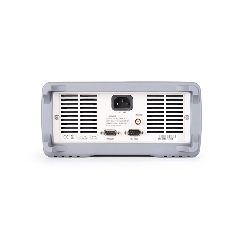
▪ Software control and testing via computer
■ HANDLER interface for easy automation matching
■ SCPI command protocol
■ power supply category
Charger, switching power supply, communication power supply, LED driver, cell phone battery, rechargeable treasure, etc.
■ new energy
Solar Cells, New Power Vehicles, Electric Bicycles
■ Electronic Power Components
Fuses / Connectors / Relays / Sensors
■ Automation equipment integration testing
| standard equipment | |||||
| Accessory Name | model number | ||||
| Test Leads at Both Ends | TH26004C | ||||
| optional | |||||
| Accessory Name | model number | ||||
Recommended


