 Comprehensive test and measurement service provider-Shenzhen Weike Electronic Technology Co.
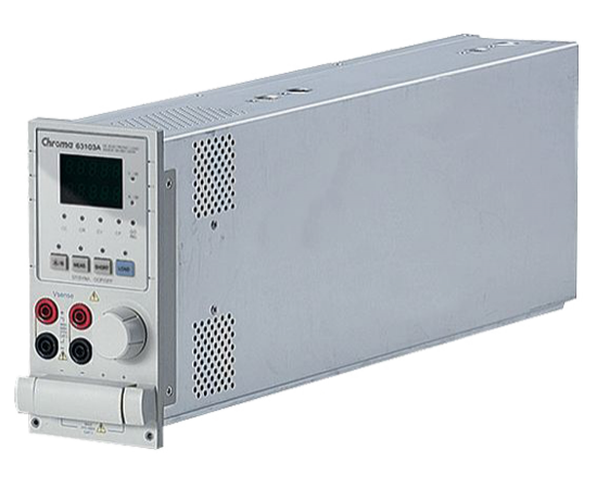


LED Driver is a current source, so it has a range of output voltage and a fixed output current. The following methods are commonly used for testing LED Drivers:
- Use a real resistor as a load.
- Operate in constant resistance (CR) mode or constant voltage (CV) mode using a conventional electronic load.
- Use real LEDs in series as loads.
However, all these test methods have their drawbacks and cannot be fully suitable for the testing needs of LED Drivers.
 ▲ LED I-V Characteristic Curve |
From the V-I characteristic curve of the LED (left), it can be seen that the LED has a forward bias voltage VF and an on-resistance (Rd). When loaded with a real resistor, the V-I characteristic is a straight line and cannot simulate the characteristics of the LED. Especially when the LED Driver's power-on voltage rises, the current waveform is different and may not be able to power on. The CR and CV modes of traditional electronic loads are based on the LED operating point at steady state as the set value, and cannot simulate the characteristics of switching or PWM dimming dynamics, which may also lead to abnormal actions or protection of the LED Driver. If the LED is used as the load, although it can completely test the LED Driver, but there are LED aging problems, and LED Driver different output voltage test, you need to connect a different number of LEDs in series, which will cause inconvenience in the test and production.
|
The 63110A/63113A of Zhimao's 6310A series electronic loads have created a new operation mode - LED mode to simulate LEDs, which allows users to simulate the pull-load characteristics of LEDs by setting the LED power supply's output voltage, current, and the LED's dynamic resistance at the operating point, and also setting the LED's operating point impedance and high-frequency impedance to make the pull-load current and high-frequency continuity closer to the real LEDs. The operating point impedance and high-frequency impedance of the LED can also be set, so that the pull current and high-frequency continuum can be more similar to that of a real LED, and for PWM dimming test, the bandwidth of the new design of the 63110A has been increased to allow users to complete dynamic dimming test with an electronic load.

Figure 2 is the LED as a load to pull the load current waveform (blue); Figure 3 for the 63110A LED mode pull the load current waveform (blue); Figure 2 and Figure 3 can be observed in both the LED power supply in the power-on pull the load voltage and current waveforms are very similar. Figure 4 for the measurement of LED as a load in the dimming current waveforms. Figure 5 for the 63110A for the load in the dimming current waveforms.
 ▲ (Fig. 2) With LED as the load |
 ▲ (Fig. 3) is the LED mode of the 63110A for loads |
 ▲ (Fig. 3) With LED as the load |
 ▲ (Fig. 4) With 63110A as the load |
The output ripple current of the LED power supply can be simulated by adjusting the internal resistance (Rr) of the 63110A. Conventional electronic loads cannot simulate the output ripple current of an LED power supply, as shown in Figure 6. Figure 7 shows the riffle current when the LED is loaded. Figure 8 shows the ripple current of the 63110A when loaded. Fig. 9 and Fig. 10 show the turn-on waveforms when using real resistors and electronic loads, respectively.
 ▲ (Fig. 6) Ripple current under conventional electronic load test |
 ▲ (Fig. 7) Ripple current under test with LED as load |
 ▲ (Fig. 8) Ripple Current under Test with 63110A as Load |
 ▲ (Fig. 9) Load with real resistance |
The current in Figure 10 is quite different from the current waveform of the LED as a load (Figure 2), and the current and voltage are overshooting, which can easily lead to over-voltage or over-current protection of the LED power supply at power-on, as shown in Figure 11. Therefore, regardless of the real resistance or electronic load of the fixed resistance mode, are less able to simulate the real situation. Figure 12 represents the simulation of different numbers of LEDs; Figure 13 represents the simulation of LEDs with different characteristics.
 ▲ (Fig. 10) Load in Constant Resistance Mode |
 ▲ (Fig. 11) Load with real resistance (LED power driver cannot be turned on) |
 ▲ (Fig. 12) Simulation of different number of LEDs |
 ▲ (Fig. 13) LED simulation with different characteristics |
| model number | relate (a story or information) |
| 63110a / 63113a / 63115a | LED Emulation Load |
| 63110A | LED emulation load 500V/2A/100W x2 channels |
| 63113A | LED Emulation Load 300V/20A/300W |
| 63115A | LED Emulation Load 600V/20A/300W |
| 6312A | Dual Load Module Bezel |
| 6314A | Four load module outer frame |
| A631000 | 6314A and 6312A control adapter with GPIB |
| A631003 | 6314A and 6312A control adapter with USB |
Recommended


