 Comprehensive test and measurement service provider-Shenzhen Weike Electronic Technology Co.
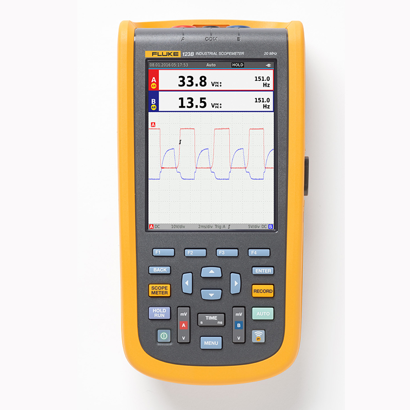


Product Overview: Fluke 120B Series ScopeMeter® Industrial Handheld Oscillometers
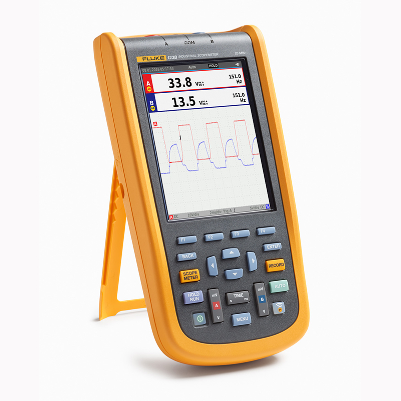
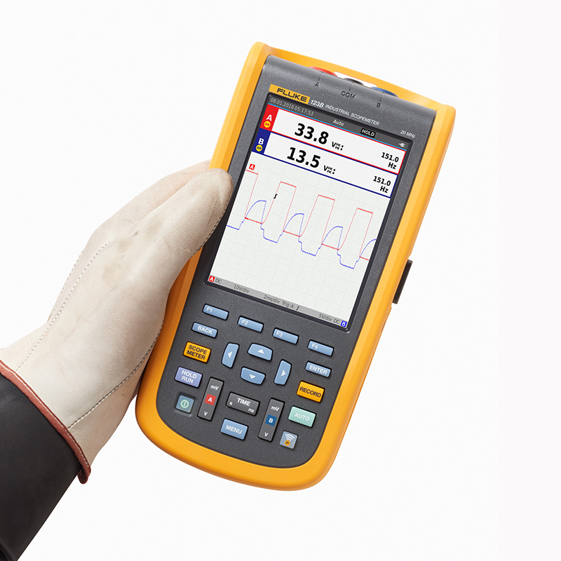
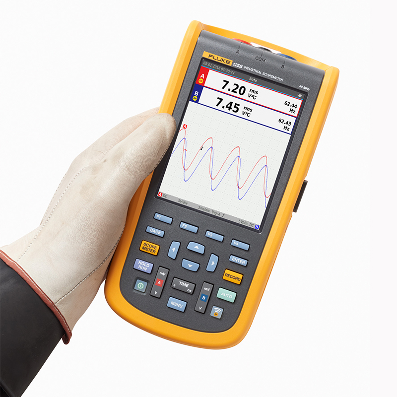
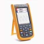
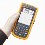
Simplified testing for deeper, faster electromechanical troubleshootingThe ScopeMeter® 120B Series is a compact, ruggedized oscilloscope for industrial electrical and electromechanical equipment troubleshooting and maintenance applications. An easy-to-use test tool that combines an oscilloscope, multimeter, and high-speed recorder, the ScopeMeter 120B Series is also compatible with the Fluke Connect® mobile app and FlukeView®, which enables in-depth collaboration, data analysis, and archiving of critical test information through ScopeMeter software.
Connect-and-View™ Triggering for Instantaneous, Stable Displays
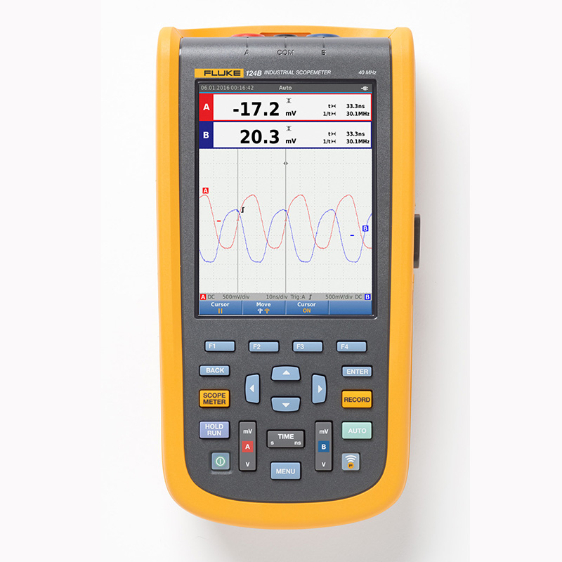
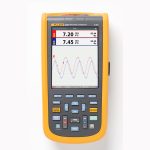
Oscilloscope users know how difficult triggering can be. Using the wrong settings can result in unstable waveform capture and sometimes even incorrect measurement data. Fluke's unique Connect-and-View™ triggering technology recognizes signal characteristics and automatically sets the correct trigger to provide a stable, reliable, and repeatable display.Connect-and-View™ triggering is specifically designed to work with virtually any signal, including motorized drive and control signals-without the need for parameter adjustments or even the touch of a button. Signal changes are immediately recognized and settings are automatically adjusted to provide a stable display, even for fast, continuous measurements of multiple test points.
IntellaSet™/Automatic Readout
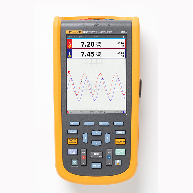
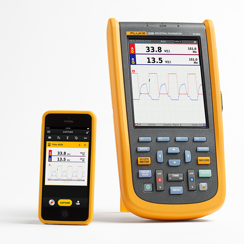
With Fluke IntellaSet™ technology's Auto-Read feature, a dedicated algorithm intelligently analyzes the measurement waveform and automatically displays the appropriate measurement value on the screen, making it easier than ever to get the data you need. For example, when the measurement waveform is a line voltage signal, the Vrms and Hz readings are automatically displayed, but if the measurement waveform is a square wave, the V peak-to-peak and Hz readings are automatically displayed. With IntellaSet™ technology and Connect-and-View™ automatic triggering, you not only get the right waveform, you get the right reading. There's no need to touch a button.
With Fluke Connect-and-View™ and IntellaSet™ technology, you can quickly access the data you need.
Industrial equipment requires a reliable power supply for proper operation, and the dual inputs enable critical power measurements to be obtained.
For single-phase or three-phase balanced systems, the dual inputs of the industrial ScopeMeter® 120B Series are capable of measuring ac+dc rms voltage on channel A and ac+dc rms current on channel B. The Fluke 125B will then calculate; frequency, active power (kW), reactive power (VA or var), or displacement power factor (PF). The Fluke 125B then performs calculations; frequency, phase angle, active power (kW), reactive power (VA or var), power factor (PF) or displacement power factor (DPF), as well as calculating the power value of a three-phase system when all phases have the same voltage and current. This can be applied to balanced systems and resistive loads.
Easy access to critical power characteristics to verify system power.
Harmonic Measurement
Harmonics are periodic distortions of voltage, current or power sinusoids. Harmonics in distribution systems are usually caused by nonlinear loads such as switched DC power supplies and adjustable speed motor drives. Harmonics can cause transformers, conductors and motors to overheat. In the harmonics function, the test tool measures up to the 51st fundamental. Measurements can also be made on DC components, THD (Total Harmonic Distortion) and K-factor, giving a complete picture of the electrical state of healthy loads.
Harmonic spectrum overview with cursor measures the percentage of distortion relative to the fundamental.
Easily Diagnose Intermittent Faults with Comprehensive Recording Mode
Hard-to-find faults are those that occur occasionally - intermittent events. These intermittent failures can be caused by improper connections, dust, dirt, corrosion, broken wires, or broken connectors. Other factors such as line breaks, arc droop, or motor startup and shutdown can also trigger intermittent events that can cause the unit to shut down. When these things happen, you may not be able to detect them right in the field. But these failures are easy to spot with the Fluke ScopeMeter® test tool. You can plot the minimum and maximum values of peak measurements or record waveform traces. Meanwhile, up to 14 days of operation can be recorded on an expandable micro SD memory card. The recorder is also equipped with Recorder Event Detect, making it even more powerful and easier than ever to detect and record intermittent faults. Simply set a queue for meter readings or oscilloscope traces to mark deviations as unique events. You can easily identify faults without having to retrieve large amounts of data and quickly move from one flagged event to the next, while still having access to the complete data set.
Quickly display recorded events so that intermittent faults can be identified and resolved.
Industrial BusHealth Test determines the quality of electrical signals in industrial buses.
BusHealth Test analyzes the electrical signals of an industrial bus or network and gives a clear indication of "good", "weak" or "bad" for all relevant parameters. This is displayed next to the actual measured values. Depending on the selected bus type (CAN-bus, Profi-bus, Foundation fieldbus, RS-232, etc.), the measured values are compared with standard values or, if different tolerances are required, unique reference values can be set. The Fluke 125B verifies the quality of electrical signals as they pass through the network, without having to look at the data content. In addition, the 125B checks signal level and speed, transition times, and distortion, and compares these to appropriate standards to help you detect errors such as improper line connections, poor contacts, grounding errors, or incorrect terminators.
Quickly understand the analog characteristics of the physical layer of industrial fieldbus signals.
Multiple electrical parameters can be measured with one test lead
High-frequency waveform, meter, capacitance, and resistance measurements can be accomplished with only one set of shielded test leads, along with on-off checks. No need to waste time searching for or replacing leads.
In addition to displaying waveforms, a single test tool can measure volts, ohms, amps, or capacitance.
FlukeView® ScopeMeter® Software for Windows
Use the ScopeMeter 120B with FlukeView® software for even more functionality:
- Save a color screenshot of your device to a PC
- Attach screenshots to your reports and documents
- Capture waveform data with the ScopeMeter test tool and save it to your PC
- Create and archive waveform references for easy comparison
- Copy waveform data into a spreadsheet for your detailed analysis.
- Parameter measurement using the cursor
- Adds user comments to instrument settings and sends them to the device for operator reference and use as operating instructions
Note: Some features are limited to specific ScopeMeter Test Tool models.
- Fluke Connect Mobile App Compatibility
Troubleshooting automated industrial machinery is more difficult than ever. It's not enough to know where to test, you also need to know what to look for - which can be especially difficult without baseline measurements or access to experts in the field. Fluke Connect® Assets wireless software systems and wireless test tools help technicians dramatically reduce maintenance costs and increase equipment uptime by delivering accurate equipment records and maintenance data that's easy to interpret and share. Increase equipment uptime. By comparing and contrasting test point measurements and trends, you can get a more complete picture of signal characteristics and changes over time. And by storing maintenance data in the Fluke Cloud™, your team members can access it when and where they need it, so you can get recommendations or approvals in the field and get systems back up and running faster than ever before.
| Product Comparison Chart | Fluke 123B | Fluke 124B | Fluke 125B |
| functionality | |||
| Full-featured Dual-Input Oscillometers and Meters | - | - | - |
|---|---|---|---|
| Oscilloscope bandwidth (MHz) | ="20" | ="40" | ="40" |
| Meter and Oscilloscope Recorder | - | - | - |
| Oscilloscope Cursor Measurement | - | - | |
| Power and Harmonic Measurements | - | ||
| BusHealth | - | ||
| Including annexes | |||
| 10:1 Voltage Probe | - | - | |
| i400S AC Current Clamp | - | ||
Product Specification: Fluke 120B Series ScopeMeter® Industrial Handheld Oscilloscope
Test Leads CatIV, 750 Vrms Max. CatIV, 750 Vrms Max. 400Hz
| Oscilloscope Mode | ||
| perpendicular | ||
| Frequency Response - DC Coupling | Without probe and test leads (with BB120) | 123B: DC max. 20 MHz (-3 dB) 124B and 125B: DC up to 40 MHz (-3 dB) |
| Equipped with STL120-IV 1:1 Shielded Test Leads | DC - 12.5 MHz (-3 dB)/DC - 20 MHz (-6 dB) | |
| With VP41 10:1 probe | 123B: DC max. 20MHz (-3 dB) 124B and 125B: DC up to 40 MHz (-3 dB) |
|
| Frequency Response - AC Coupling (if tipped over) | Without probes and test leads | <10 Hz (-3 dB) |
| Equipped with STL120-IV 1:1 Shielded Test Leads | <10 Hz (-3 dB) | |
| With VP41 10:1 probe | <10 Hz (-3 dB) | |
| Rise time, without probe. | 123B <17.5 ns 124B and 125B <8.75 ns |
|
| Input Impedance | Without probes and test leads | 1 MΩ//20 pF |
| Equipped with BB120 | 1 MΩ//24 pF | |
| Equipped with STL120-IV 1:1 Shielded Test Leads | 1 MΩ//230 pF | |
| With VP41 10:1 probe | 5 MΩ//15.5 pF | |
| (level of) sensitivity | 5 mV to 200 V/div | |
| Analog Bandwidth Limiter | 10 kHz | |
| display mode | A, -A, B, -B | |
| Maximum input voltages A and B | Direct input with test leads or with VP41 probe | 600 Vrms |
| Equipped with BB120 | 600 Vrms | |
| Maximum no-load voltage between any terminal and grounding | 600 Vrms | |
| level (of achievement etc) | ||
| Oscilloscope Mode | Standard, single, rotating | |
| Scope (standard) | equivalent sampling | 123B: 20 ns to 500 ns/div. |
| 124B and 125B: 10 ns to 500 ns/div | ||
| Real-time sampling | 1 μs to 5 s/div | |
| Single (real-time) | 1 μs to 5 s/div | |
| Rotation (real time) | 1 s to 60 s/div | |
| Sampling rate (dual channel simultaneous sampling) | Equivalent Sampling (Repeat Signal) | Up to 4 GS/s |
| Real-time sampling 1 μs to 60 s/div | 40 MS/s | |
| trig | ||
| screen update | Autorun, Trigger | |
| data sources | A, B | |
| A and B sensitivity | @ DC - 5 MHz | 0.5 div or 5 mV |
| @ 40 MHz | 123B: 4 div | |
| 124B and 125B: 1.5 cells | ||
| @ 60 MHz | 123B: N/A | |
| 124B and 125B: 4 compartments | ||
| slope | Positive, Negative | |
| Advanced Oscilloscope Features | ||
| display mode | normalcy | Captures pulse wave interference up to 25 ns and displays continuous waveforms similar to analog signals |
| smoothness | Suppression of waveform noise | |
| Pulse wave interference capture off | Does not capture inter-sample pulse wave interference | |
| envelope | Records and displays waveform minimum and maximum values over a period of time | |
| Automatic Setup (Connect-and-View™) | Fully automatic continuous adjustment of amplitude, time base, trigger level, trigger interval and delayed trigger. The user can manually override by adjusting the amplitude, time base or trigger level. | |
Uncertainty +1%. it must be possible to display multiple waveform periods on the screen.
| Dual Input Meter | ||
| The accuracy of all measured values is between (% of the reading + last significant digit) at temperatures between 18 °C and 28 °C. | ||
| Below 18 °C or above 28 °C, add 0.1x (specific accuracy) for each 1 °C decrease or increase. For voltage measurements with a 10:1 probe, add the probe's |
| Input A and Input B | ||
| DC Voltage (VDC) | ||
| range (of scales or measuring equipment) | 500 mV, 5 V, 50 V, 500 V, 750 V | |
| precision | ± (0.5% + 5 counts) | |
| Common mode rejection ratio (CMRR) | >100 dB @ dc, >60 dB @ 50, 60 or 400 Hz | |
| full scale reading | 5000 count | |
| True RMS voltage (V ac and V ac+dc) | ||
| range (of scales or measuring equipment) | 500 mV, 5 V, 50 V, 500 V, 750 V | |
| Accuracy Range of 5% - 100% (DC coupled) | DC - 60 Hz (V ac+dc) | ± (1% +10 counts) |
| 1 Hz - 60 Hz (V ac) | ± (1% +10 counts) | |
| Accuracy 5% - 100% of range (AC or DC coupled) | 60 Hz to 20 kHz | ± (2.5% +15 counts) |
| DC rejection (VAC only) | >50 dB | |
| Common mode rejection ratio (CMRR) | >100 dB @ dc | |
| >60 dB @ 50, 60 or 400 Hz | ||
| full scale reading | 5000 counts, the readings are independent of the crest factor of any signal. | |
| peak value | ||
| paradigm | Maximum peak, minimum peak, or peak-to-peak value | |
| range (of scales or measuring equipment) | 500 mV, 5 V, 50 V, 500 V, 2200 V | |
| precision | Accuracy of maximum peak or minimum peak | 5% at full scale |
| Peak-to-peak accuracy | 10% at full scale | |
| full scale reading | 500 count | |
| Frequency (Hz) | ||
| range (of scales or measuring equipment) | 123B: 1 Hz, 10 Hz, 100 Hz, 1 kHz, 10 kHz, 100 kHz, 1 MHz, 10 MHz and 50 MHz | |
| 124B and 125B: 1 Hz, 10 Hz, 100 Hz, 1 kHz, 10 kHz, 100 kHz, 1 MHz, 10 MHz, and 70 MHz | ||
| frequency range | 15 Hz (1 Hz) to 50 MHz in continuous auto setting | |
| 1 Hz to 1 MHz accuracy | ± (0.5% + 2 counts) | |
| full scale reading | 10,000 times | |
| RPM | ||
| Maximum reading | 50.00 kRPM | |
| precision | ± (0.5% + 2 counts) | |
| Duty Cycle (PULSE) | ||
| range (of scales or measuring equipment) | 2% to 98% | |
| frequency range | 15 Hz (1 Hz) to 30 MHz in continuous auto setting | |
| Pulse Width (PULSE) | ||
| frequency range | 15 Hz (1 Hz) to 30 MHz in continuous auto setting | |
| full scale reading | 1000 count | |
| Current (AMP) | ||
| Equipped with current clamp | range (of scales or measuring equipment) | Same as V dc, V ac, V ac+dc or PEAK |
| proportionality factor | 0.1 mV/A, 1 mV/A, 10 mV/A, 100 mV/A, 400 mV/A, 1 V/A, 10 mV/mA | |
| precision | Same as V dc, V ac, V ac+dc or PEAK (plus current clamp uncertainty) | |
| Temperature (TEMP) with optional temperature probe | ||
| range (of scales or measuring equipment) | 200 °C/div (200 °F/div) | |
| proportionality factor | 1 mV/ °C and 1 mV/ °F | |
| precision | Same as V dc (plus temperature probe uncertainty) | |
| Decibel (dB) | ||
| 0 dBV | 1 V | |
| 0 dBm (600 Ω /50 Ω) | 1 mW at 600 Ω or 50 Ω reference condition | |
| dB on | V dc, V ac or Vac+dc | |
| full scale reading | 1000 count | |
| Crest Factor (CREST) | ||
| range (of scales or measuring equipment) | 1 to 10 | |
| full scale reading | 90 Count | |
| phase (waves) | ||
| paradigm | A-B, B-A | |
| range (of scales or measuring equipment) | 0 to 359 degrees | |
| resolution (of a photo) | 1 degree | |
| Power (125B only) | ||
| configure | Single-phase/three-phase, three-wire balanced loads (three-phase: fundamental components only, "auto-set" mode only) | |
| Power Factor (PF) | Ratio between wattage and volt-ampere range - 0.00 to 1.00 | |
| watt (loan) | RMS reading obtained by multiplying the corresponding sampled values of input A (volts) and input B (amps) | |
| full scale reading | 999 count | |
| VA | Vrms x Arms | |
| full scale reading | 999 count | |
| Reactive power (VAR) | √((VA)²-W²) | |
| full scale reading | 999 count | |
| Vpwm | ||
| goal | Measurement of pulse width modulated signals, e.g. motor drive inverter output signals | |
| principle | The reading shows the effective voltage based on the average of samples taken over the entire number of cycles of the fundamental frequency. | |
| precision | Vrms for sine wave signals | |
| Input A to Common | ||
| Ohm (Ω) | ||
| range (of scales or measuring equipment) | 123B and 124B | 500 Ω, 5 kΩ, 50 kΩ, 500 kΩ, 5 MΩ, 30 MΩ |
| 125B | 50 Ω, 500 Ω, 5 kΩ, 50 kΩ, 500 kΩ, 5 MΩ, 30 MΩ | |
| precision | ± (0.61 TP3T + 5 counts) 50 Ω ± (21 TP3T + 20 counts) | |
| full scale reading | 50 Ω to 5 MΩ - 5000 counts, 30 MΩ - 3000 counts | |
| measured current | 0.5 mA to 50 nA, decreasing with increasing range | |
| open circuit voltage | <4 V | |
| On-off (Cont) | ||
| beeping | < (30 Ω ± 5 Ω) at 50 Ω range | |
| measured current | 0.5 mA | |
| Short circuit detected | ≥1 ms | |
| thyristor | ||
| measured voltage | 0.5 mA | >2.8 V |
| open circuit | <4 V | |
| measured current | 0.5 mA | |
| polarities | Input A is + pole, COM is - pole | |
| Capacitance (CAP) | ||
| range (of scales or measuring equipment) | 50 nF, 500 nF, 5 μF, 50 μF, 500 μF | |
| full scale reading | 5000 count | |
| measured current | 500 nA to 0.5 mA, increases with range | |
| Advanced Meter Functions | ||
| Zero Setting | Setting the actual value based on the reference value | |
| Auto Hold (Input A) | Captures and maintains stable measurements. A beep sounds when the measurement stabilizes. The Auto Hold function applies to the main meter reading where the AC signal threshold is 1 Vpp and the DC signal threshold is 100 mV. | |
| Fixed decimal point | Use the attenuation key to enable | |
(Auto-leveling only)
| Cursor readout (124B and 125B) | ||
| data sources | A, B | |
| single vertical line | Average, minimum and maximum readings | |
| Average reading, minimum reading, maximum reading and time since start of reading (in "scroll" mode, meter in "hold" mode) | ||
| Minimum reading, maximum reading and time since start of reading (in "logger" mode, meter in "hold" mode) | ||
| Harmonic values in "Power Quality" mode. | ||
| double vertical line | Peak-to-peak, time-distance and time-distance inverse readings | |
| Average, minimum, maximum and time-distance readings (in "scroll" mode, meter in "hold" mode) | ||
| bizontal line | High, low and peak readings | |
| Rise or fall time | Transition time, 0% and 100% readings (manual or auto-leveling; single-channel mode) | |
| precision | Same accuracy as an oscilloscope | |
| logger | ||
| The recorder captures meter readings in Meter Recorder mode or continuously samples waveforms in Scope Recorder mode. Information is stored in memory or on an optional SD card (Model 125B or 124B). | ||
| The measurement results are displayed on the graphic recorder as a graph of the meter's maximum and minimum measurements over time, and on the waveform recorder as a graph of the samples taken. | ||
| meter reading | ||
| Measurement speed | Up to 2 measured values/second | |
| Record size (minimum, maximum, average) | 1 channel 2 M readings | |
| Recording time span | 2 weeks | |
| Maximum number of events | 1024 | |
| waveform recording | ||
| Maximum sampling rate | 400 K samples/second | |
| Size Memory | 400 M Sampling Recording Time | |
| Spanning Memory | 500 μs/div for 15 minutes 20 ms/div for 11 hours |
|
| Record size SD card | 1.5 G sampling | |
| Recording time span SD card | 500 μs/div for 11 hours 20 ms/div for 14 days |
|
| Maximum number of events | 64 | |
(Basic 40 Hz to 70 Hz)
| Power quality (125B only) | ||
| readings | w, va, var, pf, dpf, hz | |
| W, VA, var Range (auto) | 250 W to 250 MW, 625 MW, 1.56 GW | |
| When selected: total harmonics (% r) | ± (2% + 6 counts) | |
| When selected: Base wave (% f) | ± (4% + 4 counts) | |
| DPF | 0.00 to 1.00 | |
| power factor | 0.00 to 1.00, ±0.04 | |
| frequency range | 10.0 Hz to 15.0 kHz 40.0 Hz to 70.0 Hz |
|
| harmonic number (e.g. number of harmonics) | DC - 51 | |
| Readout/cursor readout | Vrms / Arms /W | Individual harmonics of the fundamental can be selected to obtain individual readings |
| Includes fundamental frequency, phase angle, and K-factor (in amps or watts) | ||
| BusHealth Tester (Fluke 125B only) | ||
| typology | subtype | protocols |
| AS-i | NEN-EN50295 | |
| CAN | ISO-11898 | |
| Interbus S | RS-422 | EIA-422 |
| Modbus | RS-232 | RS-232/EIA-232 |
| RS-485 | RS-485/EIA-485 | |
| Foundation Fieldbus | H1 | 61158 Category 1, 31.25 kBit |
| Profibus | DP | EIA-485 |
| PA | 61158 Category 1 | |
7 hours (screens, waveforms, and settings) when test tool is turned off (32 GB maximum)
(10.2 x 5.2 x 2.15 in) FlukeView® software.
| Other specifications | ||
| monitor | typology | 5.7-inch color active matrix TFT |
| resolution (of a photo) | 640 x 480 pixels | |
| waveform display | perpendicular | 10 frames of 40 pixels |
| level (of achievement etc) | 12 frames of 40 pixels | |
| power (output) | externally | Via BC430 power adapter |
| Input Voltage | 10 V DC to 21 V DC | |
| power wastage | 5 W Standard | |
| Input Connector | 5 mm Sockets | |
| inside (part, section) | Via BP290 Battery Pack | |
| Battery Power | 10.8 V lithium-ion rechargeable battery | |
| working hours | 7 hours (50% backlight brightness) | |
| charging time | 4 hours when the test tool is shut down | |
| Permissible ambient temperature | 0 to 40 °C (32 to 104 °F) when charged | |
| data storage | Internal memory class for 20 data sets | Micro SD card slot with optional SD card |
| (old) cunning | sizes | 259 x 132 x 55 mm |
| weights | 1.4 kg (3.2 lb) w/batteries | |
| connector | optically isolated interface | Transfer screenshots (bitmaps), settings and data |
| USB interface for PC/laptop connection | OC4USB Opto-Isolated USB Adapter/Cable (Option) with Windows® Edition | |
| Optional WiFi adapter | Quickly transfer screenshots (bitmaps), settings and data to PCs/laptops, tablets, smartphones and more. A USB port is provided for connection to a WiFi receiver. For safety reasons, do not use the USB port by wiring. | |
Group 1, Class A IV, 750 Vrms 400 Hz max.
| operating environment | ||
| operating environment | MIL-PRF-28800F Class 2 | |
| temp | Battery operation | 0 to 40 °C (32 to 104 °F) |
| Working with the power adapter | 0 to 50 °C (32 to 122 °F) | |
| leave in sb's care | -20 to 60 °C (-4 to 140 °F) | |
| Operating humidity | At 0 to 10 °C (32 to 50 °F) | non-condensing |
| At 10 to 30 °C (50 to 86 °F) | 95% | |
| At 30 to 40 °C (86 to 104 °F) | 75% | |
| At 40 to 50 °C (104 to 122 °F) | 45% | |
| leave in sb's care | -20 to 60 °C (-4 to 140 °F) | non-condensing |
| height above sea level | Operating altitude of 3 km (10,000 feet) | CAT III 600 V |
| Operating altitude of 2 km (6,600 feet) | CAT IV 600 V | |
| leave in sb's care | 12 km (40,000 feet) | |
| EMC Electromagnetic Compatibility | international standard | IEC 61326-1: Industry, CISPR 11: |
| Korea (KCC) | Class A equipment (industrial broadcasting and communications equipment) | |
| United States (FCC) | 47 CFR 15 Subpart B. This product is considered tax-exempt equipment under Section 15.103. | |
| Radio with adapter | frequency range | 2412 MHz to 2462 MHz |
| output power | <100 mW | |
| protection class | IP51, reference: EN/IEC60529 | |
| security level | common (use) | IEC 61010-1: Pollution class 2 |
| surveying | IEC 61010-2-033: CAT IV 600 V/CAT III 750 V | |
| Maximum input voltages A and B | Direct input or via line input | Derating 600 Vrms CAT IV |
| Equipped with Banana-to-BNC Adapter BB120 | Derating 600 Vrms | |
| Maximum no-load voltage between any terminal and grounding | 600 Vrms Cat | |
Model: Fluke 120B Series ScopeMeter® Industrial Handheld Oscilloscope
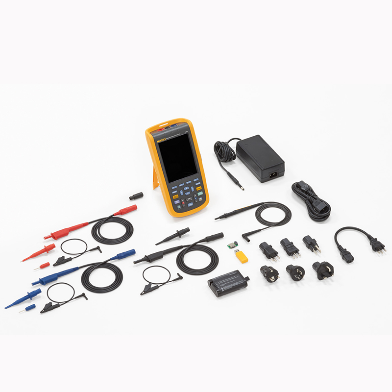
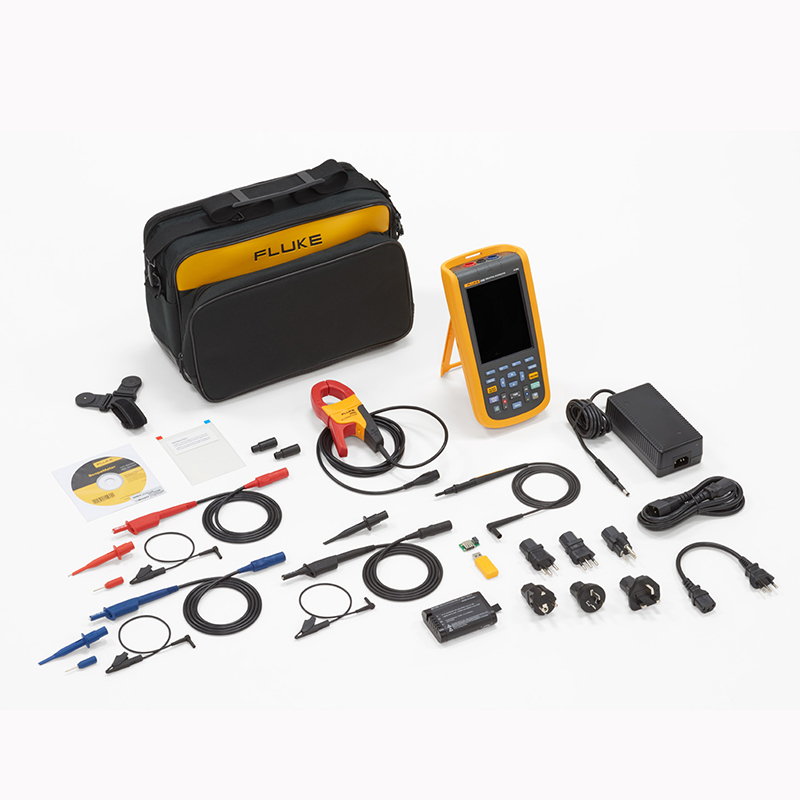
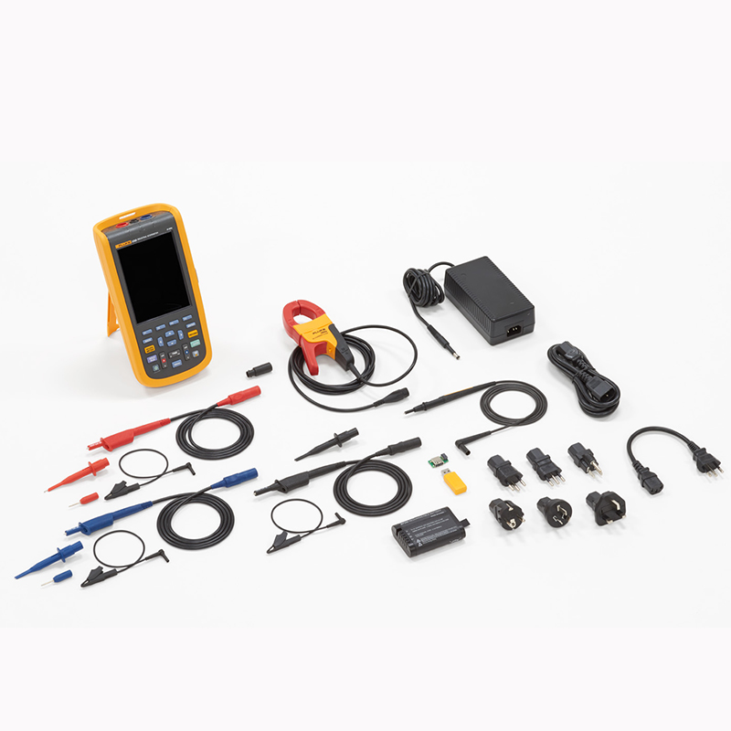
FLUKE-125B/CN
Scope Meter® Industrial Handheld Oscilloscope (40 MHz)
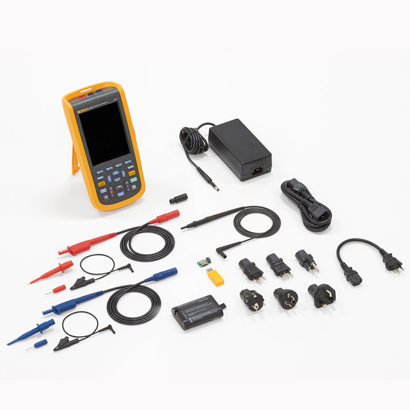
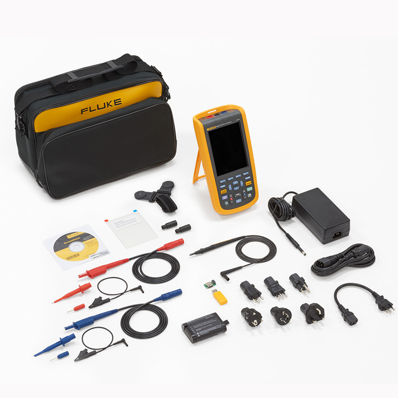
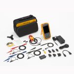
Included:
- Fluke 125B Handheld Oscilloscope
- Armored test leads with black ground wire
- Black Test Lead (Ground)
- Hook Test Clips (Red, Blue)
- Banana-to-BNC Adapter (Black, 1 ea.)
- 10:1 Voltage Probe
- i 400s AC Current Clamp
- USB Corner Adapter
- Wi Fi USB Adapter*
- Switch mode power supplies, adapters/battery chargers
- Rechargeable lithium-ion battery pack
FLUKE-123B/CN
Scope Meter® Industrial Handheld Oscilloscopes (20 MHz)
Included:
- Fluke 123B Handheld Oscilloscope
- Armored test leads with black ground wire
- Black Test Lead (Ground)
- Hook Test Clips (Red, Blue)
- Banana-to-BNC Adapter (Black, 1 ea.)
- USB Corner Adapter
- Wi Fi USB Adapter*
- Switch mode power supplies, adapters/battery chargers
- Rechargeable lithium-ion battery pack
FLUKE-123B/CN/S
Scope Meter® Industrial Handheld Oscilloscopes (20 MHz)
Included:
- Fluke 123B Handheld Oscilloscope
- Armored test leads with black ground wire
- Black Test Lead (Ground)
- Hook Test Clips (Red, Blue)
- Banana-to-BNC Adapter (Black, 1 ea.)
- USB Corner Adapter
- Wi Fi USB Adapter*
- Switch mode power supplies, adapters/battery chargers
- Rechargeable lithium-ion battery pack
- Portable Soft Case
- Magnetic Suspension
- Fluke View® Scope Meter® Software for Windows
- screensaver
FLUKE-124B/CN
Scope Meter® Industrial Handheld Oscilloscope (40 MHz)
Included:
- Fluke 124B Handheld Oscilloscope
- Armored test leads with black ground wire
- Black Test Lead (Ground)
- Hook Test Clips (Red, Blue)
- Banana-to-BNC Adapter (Black, 1 ea.)
- 10:1 Voltage Probe
- USB Corner Adapter
- Wi Fi USB Adapter*
- Switch mode power supplies, adapters/battery chargers
- Rechargeable lithium-ion battery pack
FLUKE-124B/CN/S
Scope Meter® Industrial Handheld Oscilloscope (40 MHz)
Included:
- Fluke 124B Handheld Oscilloscope
- Armored test leads with black ground wire
- Black Test Lead (Ground)
- Hook Test Clips (Red, Blue)
- Banana-to-BNC Adapter (Black, 1 ea.)
- 10:1 Voltage Probe
- USB Corner Adapter
- Wi Fi USB Adapter*
- Switch mode power supplies, adapters/battery chargers
- Rechargeable lithium-ion battery pack
- Portable Soft Case
- Magnetic Suspension
- Fluke View® Scope Meter® Software for Windows
- screensaver
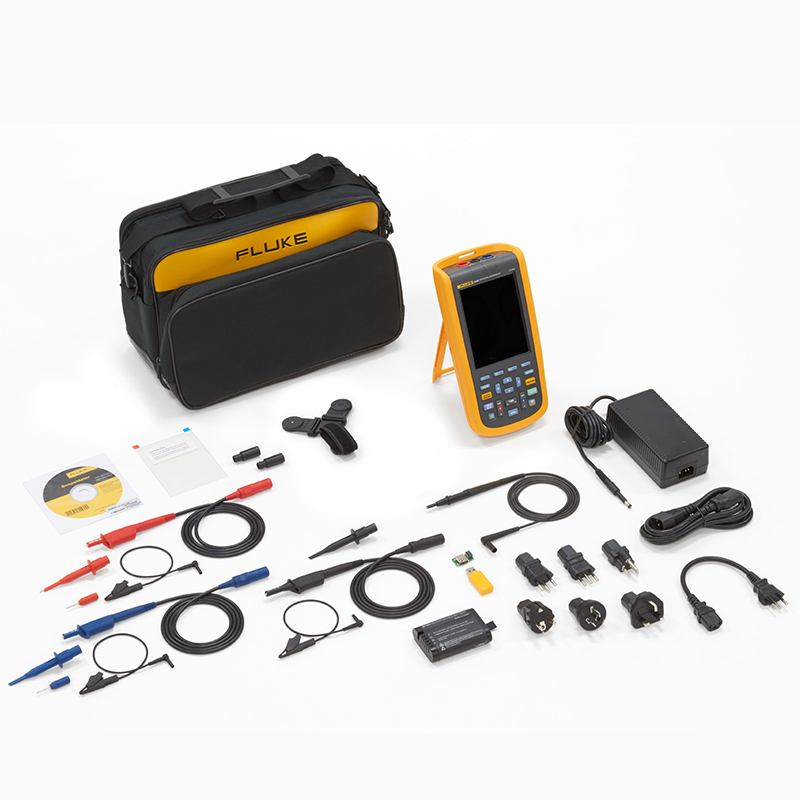
FLUKE-125B/CN/S
Scope Meter® Industrial Handheld Oscilloscope (40 MHz)
Included:
- Fluke 125B Handheld Oscilloscope
- Armored test leads with black ground wire
- Black Test Lead (Ground)
- Hook Test Clips (Red, Blue)
- Banana-to-BNC Adapter (Black, 1 ea.)
- 10:1 Voltage Probe
- i 400s AC Current Clamp
- USB Corner Adapter
- Wi Fi USB Adapter*
- Switch mode power supplies, adapters/battery chargers
- Rechargeable lithium-ion battery pack
- Portable Soft Case
- Magnetic Suspension
- Fluke View® Scope Meter® Software for Windows
- screensaver

