 Comprehensive test and measurement service provider-Shenzhen Weike Electronic Technology Co.
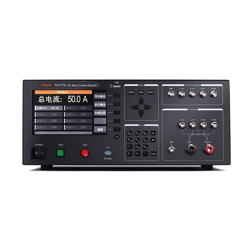

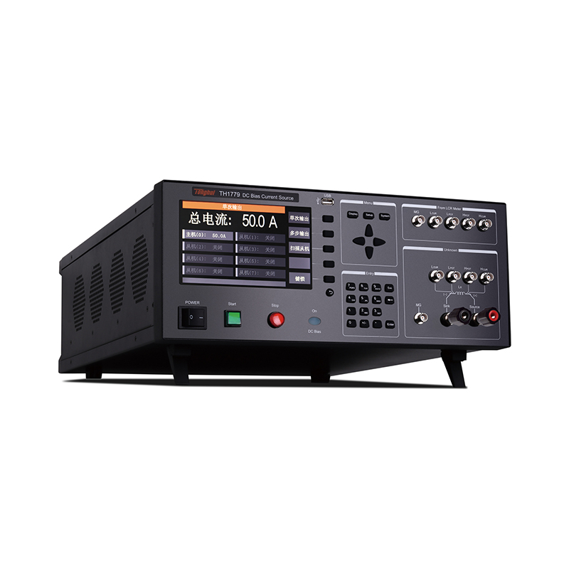
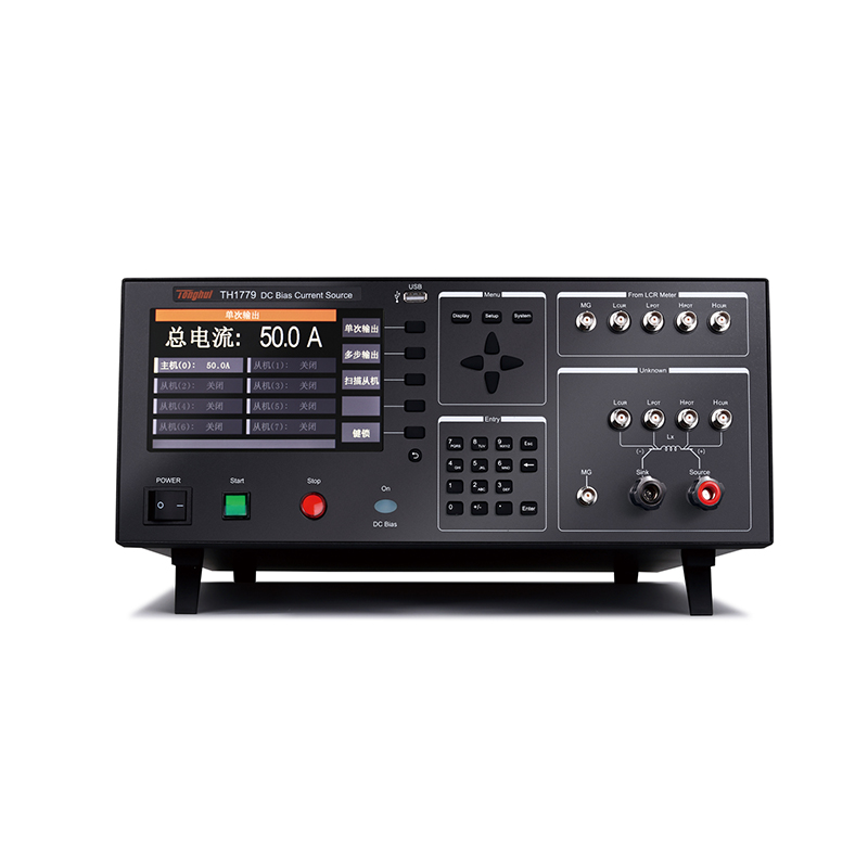
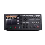
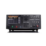


With its deep technical accumulation and extensive market research in the field of bias current source, Tonghui Electronics has launched a high power DC bias current source-TH1779 series DC bias current source.
TH1779 DC bias current source adopts high-performance microprocessor, can provide single 0.1-50A constant current output, and can be master-slave mode parallel to enhance the maximum output current to 0.1-300A, with excellent tailorability and scalability.
TH1779 DC bias current source adopts a new generation of AC/DC superposition test principle, adapting to high precision and high frequency test requirements. Built-in high-performance embedded MCU can quickly respond to the status or failure of the master and slave and real-time instructions to help improve work efficiency.
The TH1779 DC bias current source is suitable for AC/DC superposition testing of magnetic inductors and test occasions requiring high currents, and can also be used as a magnetization current source for analysis of magnetic materials.
The TH1779 DC Bias Current Source provides both physical keypad and footswitch controls to ensure operator safety, and can be used for manual control when connecting to other unspecified models of LCR digital bridges or other brands of LCR bridges with Whitney.
The TH1779 DC bias current source is equipped with a test interface that can be directly connected to our specified LCR bridges and can be directly controlled by the corresponding LCR digital bridge.
Quick Selection
| Summary parameters | TH1779 |
| client-server (computing) | One master, the rest are slaves, support up to 8 parallel machines |
| Output Current | Stand-alone: 0-50A
Parallel: 400A |
| frequency response | 0Hz-2MHz |
| open circuit voltage | 16V |
Test Signal Level Correlation for Magnetic Inductors
Signal level correlation exists for all components: component values are related to the magnitude of the signal level at a specified test frequency.
Some components are extremely sensitive to signal levels, such as ceramic capacitors with high K (high dielectric constant) values and inductors with high permeability.
Therefore, it is important to specify the measured signal level (voltage or current) for such devices. The correlation between the component and the signal level is shown in the following figure

Test Signal Level Correlation for Magnetic Inductors
Components are correlated with the DC bias voltage or bias current applied to them. The superposition of AC and DC signals is extremely common in the various uses of components. For example, the junction capacitance of diodes and transistors, high-K ceramic capacitors, electrolytic capacitors, inductors with ceramic cores or transformers. The DC voltage or current superimposed on the different parameters will cause changes, some device parameters may produce drastic changes.

As seen in the above figure, the magnetic inductance decreases as the superimposed DC bias current increases.
Since the external DC bias current is usually large, the amplitude of the DC voltage level signal at both ends of the inductor will be much larger than the amplitude of the AC level signal output by the LCR. Therefore, after superimposing the DC bias current, the AC level signal set by the LCR has basically no effect on the inductance.
In order to ensure the stability of the inductance test, it is usually sufficient to set the LCR AC level to 1V.
Technical Parameters
| model number | TH1779 | |
| client-server (computing) | Host or Slave | |
| demonstrate | monitor (computer) | 7-inch 800 x 480 RGB TFT LCD |
| interfaces | fully graphical | |
| manipulate | Physical buttons + footswitch | |
| range (of scales or measuring equipment) | 50A | |
| current step | realm | 0mA-50A |
| resolution (of a photo) | 100mA | |
| Supported Measurement Frequency | 1kHz-2MHz | |
| Current rise time | 1A/s - 20A/s, can be set arbitrarily | |
| Current drop time | 1A/s - 20A/s, can be set arbitrarily | |
| Scan Adjustment Minimum Step | 100mA | |
| Maximum Output Voltage | 16V | |
| Maximum Allowable DC Resistance | Rmax=Vmax / I (Ω) (R)max(Please refer to the user's manual for calculations) | |
| Maximum Allowable Inductance | Lmax=Vmax /(di/dt) (mH) (refer to user manual for Lmax calculation) | |
| Start and stop control mode | START/STOP physical buttons, buses, controlled by host computer | |
| Continuous loading of maximum current time | 2-3h, uninterrupted output | |
| functionality | Instrument fault self-test; Chinese and English bilingual; slave soft switch; real-time operation; SCPI instruction set, etc. | |
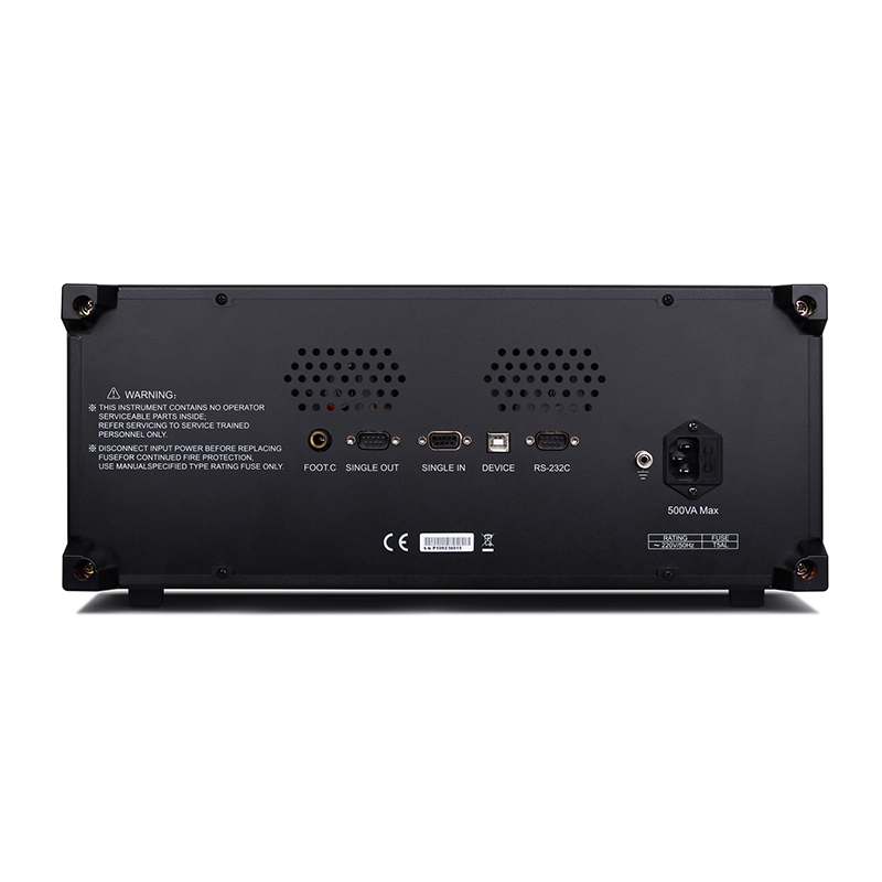
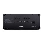
| connector | RS232, SlaverLink | |
| temp | proper functioning | 0°C-55°C |
| benchmarking | 23(±5)°C | |
| Transportation environment | 0°C-55°C | |
| humidity level | proper functioning | <90%RH |
| benchmarking | <80%RH | |
| Transportation environment | <93%RH | |
| power supply | input voltage | AC 220V/110V (±10%) |
| frequency | 50Hz/60Hz (±5%) | |
| power wastage | Standby: ≤100VA, full load: 1.5kVA | |
| Volume (mm) | Single 430W x 177H x 585D (not in cabinet volume) | |
| weights | Single unit 26.5kg (not in cabinet weight) | |
- Single 0-50A constant current output, can be used as master or slave
- Support up to 8 sets of on-line, maximum 400A constant current output
- Master/slave control mode, flexible tailorability and scalability
- Fine current stepping
- 0Hz-2MHz frequency response
- Two types of current outputs: single current and step scanning
- Graphical operation, Chinese and English interface
- Directly controlled by TH2851/TH2848/TH2840/TH2836/TH2839/TH2838 series
■ Inductor/Reactor DC Characterization
■ Iron core/ferrite material saturation characterization
■ DC characterization of other materials
Recommended


