Test engineers and developers use oscilloscopes to display, visualize graphs, and analyze electrical signals during research and development, verification, quality assurance, and troubleshooting or debugging of electronic systems, boards, and integrated circuits. Oscilloscopes play a key role in a variety of applications and technologies across all industries, including high-speed digital electronics, optical communications, radio frequency, power electronics, automotive and aerospace and defense.
Oscilloscopes are key test instruments for observing, analyzing, or recording the behavior of electrical signals. Some specific use cases for oscilloscopes in electronics labs include measuring voltage waveforms, analyzing electronic signals, detecting unwanted noise and crosstalk, and evaluating harmful transients in power systems.
In high-speed signal analysis, oscilloscopes can measure signal integrity by displaying and measuring eye diagrams, including eye height and eye width. Mixed-signal oscilloscopes can help debug digital circuits by displaying the logic state and timing of measured digital signals. Advanced oscilloscopes can even help simulate ideal reference receivers for transmitter testing, measure fiber optic signals using optoelectronic converters, and analyze RF signals.
Because of their versatility, oscilloscopes have many different performance levels and software features depending on the application. They are indispensable tools in electronics development, troubleshooting and analysis.
Signal analyzers are capable of measuring the amplitude and phase of an input signal at a single frequency. The Signal Analyzer combines the large dynamic range of a swept-tuned spectrum analyzer with the power of a Vector Signal Analyzer (VSA) to perform in-channel measurements, such as Error Vector Magnitude (EVM) measurements, which require both magnitude and phase information. The VSAs are available in a wide range of sizes and sizes.
Want to know how to use the current probe? Please first understand the following basic usage of the current probe and precautions for use. Since electricity is invisible, it is not possible to immediately determine whether a malfunction has occurred. In some cases, current measurements are required on a daily basis to prevent malfunctions, as well as to identify the cause of malfunctions when they do occur. Digital multimeters, clamp meters, and current probes can be used...
In this article, we will describe the basic measurements of an impedance analyzer. Overview An impedance tester is an instrument used to measure AC resistance or impedance. This article will introduce the basic knowledge about impedance, the measurement method of impedance, and how to use the impedance tester. What is impedance? What is impedance? In short, it is "a quantity that indicates the difficulty of the flow of alternating current". ...
An oscilloscope captures and displays signals in the time domain, while a spectrum analyzer captures and displays signals in the frequency domain. Sometimes, oscilloscopes have a built-in spectrum analyzer function to make it easy to analyze signals in both the time and frequency domains. ,
 Comprehensive test and measurement service provider-Shenzhen Weike Electronic Technology Co.
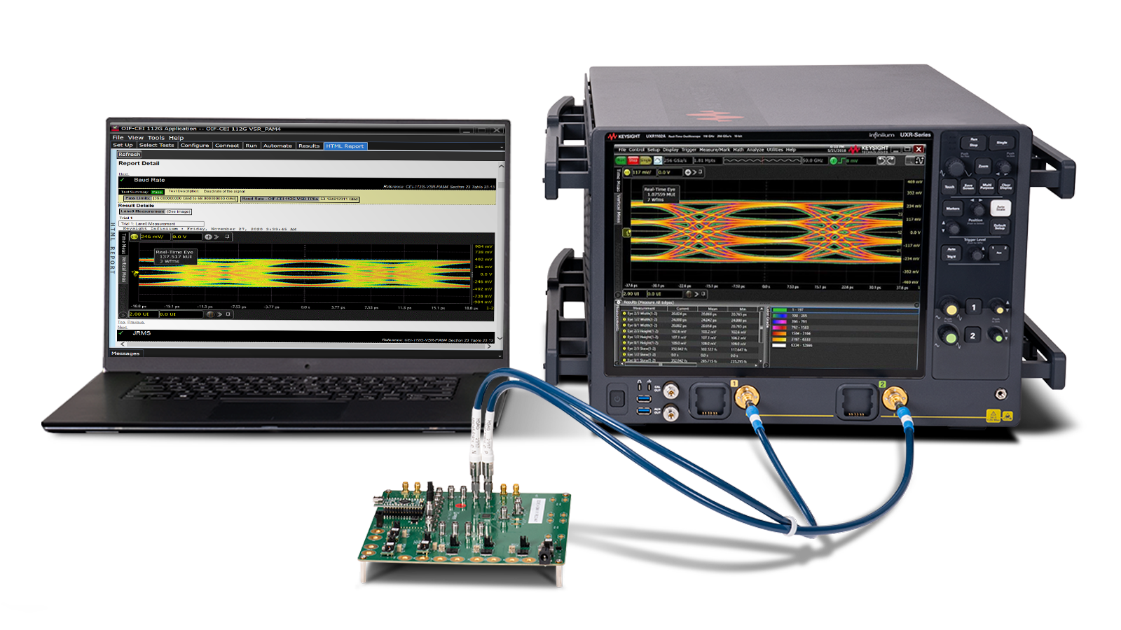


Hello!sign in