Comprehensive test and measurement service provider-Shenzhen Weike Electronic Technology Co.
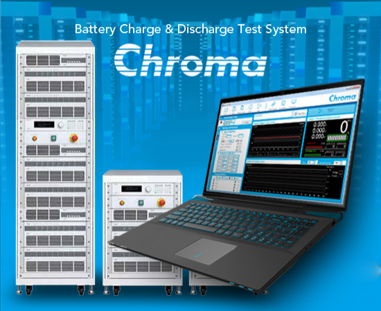


Why you need a battery emulator
More and more power conversion products are used with batteries, such as motor drives, OBCs, D-D converters in automotive systems, or converters in energy storage systems (PCS), DC bus products.... and other applications. But the product in the research and development design, its supplier battery may not be in place, or with different types of batteries, charge and discharge characteristics of different curves, liquid current batteries, sodium-sulfur batteries, lithium-iron batteries, etc., to prepare at the same time is not easy. And the battery is non-linear characteristics, the impact of temperature, charge and discharge rate, aging, efficiency, etc., can not maintain the same characteristics to repeat the test.
In addition, it takes time to charge and discharge the battery, and it is inconvenient to change the output voltage immediately to test the upper and lower limit values of the power converter. Most importantly, large-capacity batteries take up a lot of volume, and when they age after use, it takes a lot of cost to replace them, plus there is a risk of fire if the batteries are damaged and accidentally over-charged or over-discharged. Therefore, it is not recommended to set up large-capacity batteries in the laboratory, but to use a battery emulator for testing.
Automotive Systems Applications

CSS System Architecture (Standalone - DC Bus) Applications

How to choose a battery emulator
or DC power supply and DC load integration solutions
Through the DC power supply and DC load integration program can also become a battery emulator, but the main difference with the bidirectional power supply is whether there is a delay in the conversion process, if you need to test the product for the bidirectional product is recommended to use the 17020 directly, if the unidirectional architecture can be considered for the 17020 or DC power supply and DC load integration program.
| 17020 | DC Source/DC Load | |
|---|---|---|
| Power Rating | >20kW | <20kW |
| Voltage Rating | 20v, 60v, 100v, 200v, 500v | Source: 30V, 40V, 80V, 100V, 300V, 450V, 600V,1000V Load: 150V, 600V, 1200V |
| V Ripple Noise (rms) | <1%FS (Base on Voltage Range) | 8mV~1500mV (Base on Voltage Range) |
| I Ripple Noise (rms) | <1%FS (Base on Current Range) | 10 mA~270mA (Base on Current Range) |
| Interrupt During Current Transition | W/O Interrupt | Interrupt During Charge / Discharge Switch |
| Battery Simulator Software | Ready by Chroma | Create by User |
| Multi-UUT | Max 8 Channels / Min 1 Channels | 1 Channels |
| Dual-Output | 2 DC Output per-channel | 1 DC Output per-channel |
For hardware specifications, please refer to
 Energy Recovery Battery Module Test System Chroma 17020 |
Common Battery Simulation Requirements
Battery Pack Internal Resistance Influence Voltage Curve
The main task of the battery pack is to provide energy to the development of the product, but the battery energy for chemical energy needs to be charged through the charging to restore its capacity, so it needs to be charged or discharged; when the charging and discharging current is added to the battery pack at the moment, the voltage of the battery pack will be in a short period of time there is a momentary change, mainly because of the impact caused by the internal resistance of the battery pack. |
Battery Pack Voltage and SOC (State of Charge) Correlation
| Battery packs define the current capacity state of the battery through the SOC, the battery capacity corresponds to the output voltage of the battery pack, the product specifications need to be clearly defined in the definition of the input DC voltage operating range in order to design the product, so the product will correspond to the output voltage of the battery pack will be associated with the capacity of the battery state of use.
|

Battery operating voltage, full discharge voltage and protection voltage
| Products in different applications will define the battery pack use of the interval, for example, pure electric vehicles will define the battery SOC use of the interval for 0 ~ 90%, HEV defined SOC for 20 ~ 70%; because of the danger of lithium battery packs, the battery management system within the battery pack will be over-voltage (OVP, UVP) management, so the common battery use of the interval management will be over-charge voltage, Over-charge voltage, over-discharge voltage, upper operating voltage, lower operating voltage, full charge voltage, full discharge voltage, six important voltage points.
|

Battery Emulator Software
| Chroma provides a multi-channel battery emulator and a bi-directional DC power controller panel, which allows users to easily use the battery emulator function.
|

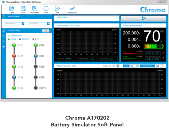
Real-time monitoring of battery emulator parameters
|

Common battery parameter setting and function simulation
 |
The software has the ability to load 4 battery cell curves to simulate the state of the battery cell at room temperature, high temperature and low temperature. |
|
 |
Battery module common parameter setting
- Simple setting of battery cell parameters into battery module status.
- Battery Pack Configuration: Set up battery cells in series and parallel to become a battery module.
- Battery Pack Internal Resistance Setting: Total Battery Internal Resistance = Battery Pack Impedance + Other Resistance (PCBA + Wire...etc.)
- Battery pack operation/protection: SOC 100%~0% setting, OVP/UVP setting, Operating range setting SOC 80%~20
 ▲Simple Setting |
 ▲ Battery Battery Pack Configuration |
 ▲ Battery pack internal resistance setting |
Output initial state setting
By setting the initial output state through the software, the desired battery state can be simulated as you wish. If you need the battery to be fully charged or SOC 50%, it can be done quickly without waiting for charging and discharging time as in the case of actual battery packs.
- Initial output state: OCV, SOC%, capacity
- Efficiency (%): software calculation results for the state considering charging efficiency and discharging efficiency
- Pre-charge voltage simulation: simulate the voltage climb state when the battery pack has the battery pack startup.

Actual output battery constant-current-to-limited-voltage (CC-CV) charging state and constant-current (CC) discharging state

| model number | relate (a story or information) |
| A170202 | Battery Emulator SoftPanel |
| 17020 | Energy Recovery Battery Module Test System |