 Comprehensive test and measurement service provider-Shenzhen Weike Electronic Technology Co.
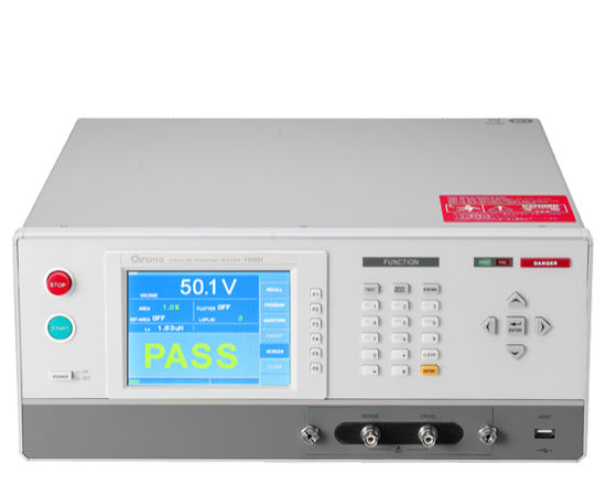
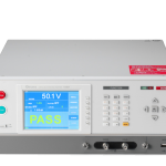
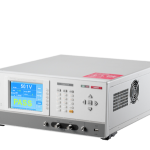


Chroma 19301A is a pulse tester for wirewound components, combining high and low inductance testing technology with 1000Vdc pulse voltage and 200MHz high speed sampling rate, providing a wide range of inductance products from 0.1uH~1mH to satisfy most of the needs of power inductance testing, and possessing waveform area size comparison, waveform area difference comparison, waveform flutter detection, waveform second-order differential detection, waveform dropout ratio detection (Laplacian), and waveform peak-to-fall ratio detection (Laplacian). With Area Size, Differential Area, Flutter, Laplacian, ΔPeak Ratio, Peak Ratio, and ΔResonant Area, it can effectively detect the defective insulation of coils. The method can effectively detect the defective insulation of the coil itself.
The production inspection of wire wound components includes testing of electrical characteristics, safety regulations and voltage resistance, while poor insulation of coils is usually the root cause of interlayer short circuits and short circuits in the coil's operating environment. The reason for this may be caused by poor initial design, poor molding process, or deterioration of the insulation material, so it is necessary to add the interlayer short circuit test to the coil.
Chroma 19301A is designed to meet the testing needs of wirewound components, using a high-voltage charging of a small capacitor (low test energy) and the coil to be tested to form a parallel resonance of the RLC, by the attenuation of the oscillating waveforms, through the high-speed and sophisticated sampling and analysis techniques, can be tested to determine the coil itself of the insulation defects, to provide power inductors to carry out the quality of the winding and the core of the withstand voltage test, so that component manufacturers and users can be more effective for product quality control. This allows component manufacturers and users to more effectively monitor product quality.
Chroma 19301A can be used for low inductance winding component testing with minimum inductance up to 0.1uH. It provides four-wire measurement, contact checking, inductance checking, and voltage compensation for low inductance testing, which can avoid large test voltage errors caused by large changes in inductance of the object to be tested or the equivalent inductance of the wiring, making it the best tool for pulse testing of low inductance winding components.
Chroma 19301A can be used in automated production with ultra-high speed measurement to shorten the test time and increase the production efficiency, and the voltage compensation function improves the effect of equivalent inductance of the automated machine wiring.
The new human-machine interface, integrated with graphical color display and screen capture function, and waveform storage via USB on the front panel, is not only applicable to the production site, but also can be applied to R&D and QA units for sample analysis and comparison, which greatly enhances the convenience of operation.
measurement technique
Introduction and Principles of Pulse Testing
"Pulse Test of Winding Components" is to apply a non-destructive, high speed, low energy voltage pulse to the object to be tested. Since the capacitor (Cs) and the winding assembly are connected in parallel, when the pulse voltage is applied to the parallel line, the capacitor and the winding assembly will generate LC resonance (Resonance), and the attenuation of resonance oscillations (Oscillations) is also known as damping to understand the process state of the coils inside the winding assembly (including the insulation of the coil itself, the inductance of the coil, and the state of the parallel capacitance (Cw)) (Figure 1: The state of test capacitance (Cw)). (including coil insulation, coil inductance and parallel connection Cw) (Figure 1: Test Equivalent Circuit Diagram). It is also possible to analyze/compare the equivalent waveforms of good and defective products under test for the purpose of determining whether they are good or not. The main function of the pulse test is to detect potential defects (e.g. short-circuiting between layers, poor electrode soldering, poor insulation of internal coils or cores, etc.) in the winding assembly at an early stage.

▲ (Fig. 1) Test Equivalent Circuit Diagrams

▲ (Fig. 2) WV Test
Rp Check
Using Peak Ratio to detect Rp size is Chroma's unique test technique to detect Rp abnormality or degradation. Some of the inductors to be tested before the test due to excessive core loss or slight core and enameled wire short-circuiting resulting in a slightly lower Q value (Rp small), after the pulse test, the switch will be open circuit (SW1 OFF) and observe the difference in the decay rate and ratio of the first peak and the second peak in the voltage oscillator waveform to detect anomalous products. The larger the value of the peak-to-peak ratio, the larger the value of Rp, and the higher the relative Q value.

▲(Fig. 3) Schematic diagram of test waveforms
Waveform Determination Mode
Waveform Area Size ComparisonThe total area of the sample and the object to be measured is compared with each other. The area is related to the insulation of the coil of the object to be measured, and a poorly insulated coil will cause a rapid decay of the waveform, so the area will be relatively small.
Waveform Area Differential AreaThe test is related to the change in the inductance of the object to be tested, and the difference in inductance will cause a change in the oscillation frequency of the coil at the back of the coil, resulting in a difference in the point-to-point area of the waveform.
Waveform Flutter DetectionThe total amount of discharge generated on the waveform is calculated by first-order differentiation and compared with the total amount of discharge of the sample waveform.
Quadratic Differential Detection of Discharge (Laplacian Value)The second-order differential algorithm, compared with the set judgment conditions, can effectively detect rapid changes in waveforms caused by electrical discharges or poor electrode welding.

▲(Fig. 4) Schematic diagram of waveform area

▲(Fig. 5) Schematic comparison of waveform area difference

▲(Fig. 6) Schematic diagram of localized discharge waveforms
Peak Ratio Detection: In the IWT BDV Test mode, the crest ratio is calculated from the first peak and the second peak of the self-resonant waveform of the object to be measured. The tolerance range of the crest ratio can be used to determine whether the test object is overly degraded. It can also be used to analyze the degradation voltage point/collapse voltage point of the test object.


▲(Fig. 7) Peak Ratio detection (Peak Ratio detection) diagram
Peak Ratio Detection (ΔPeak Ratio): In the IWT Test mode, the wave ratio is calculated from the first and second peaks of the auto-resonant waveform of the object to be measured, and this wave ratio is compared to the wave ratio of the sample. If the waveform ratios of the DUT and the sample are the same, Δ PEAK RATIO will be equal to 0%. Δ PEAK RATIO is the ratio of the difference in waveform ratios of the DUT and the sample to the waveform drop ratio of the sample. The operator can use the upper and lower limits of Δ PEAK RATIO to set a tolerance range to screen out anomalies that are significantly different from the sample.

Comparison of Resonant Area (ΔResonant Area)In the IWT Test mode, the concept and waveform area comparison is comparable to the observation of the self-resonant waveform generated by the object to be measured after the switch (SW1) is opened, and the total area of the self-resonant waveform of the object to be measured is compared with that of the sample, and the size of the area is related to the insulation of the coil of the object to be measured, and a poorly insulated coil will cause a rapid decay of the waveform, and therefore the area will be relatively small.

▲(Fig. 8) Schematic diagram of resonant wave area
Low Inductance Pulse Test Technology
Chroma 19301A is developed for low inductance wirewound components to be tested, the minimum test inductance can be 0.1uH products for the interlayer short circuit test, low inductance to be tested is different from the general inductance product testing applications, due to the low inductance of the test object to be tested, so it is easy to be affected by the equivalent inductance of the wiring on the test circuit. The test voltage is divided into the wiring lines, making the terminal voltage of the DUT far lower than the set voltage of the measurement. In addition, such as low inductance power choke, its operating voltage is applied at lower voltage, so its pulse test voltage is usually lower than the general inductance products.
low voltage range
Low inductance products, such as smart phones in the Power choke, its operating voltage is lower and smaller, can test the voltage is relatively low, so for the measurement of low inductance of the pulse test equipment needs to have a lower voltage gear for waveform analysis, Chroma 19301A has seven voltage gears were 25V, 50V, 100V, 200V, 400V, 800V and 1600V, and has a minimum voltage recognition of 0.25V, which can effectively improve the waveform to determine the ability to identify the minimum test voltage can start from 10V. The Chroma 19301A has seven voltage levels, namely 25V, 50V, 100V, 200V, 400V, 800V and 1600V, and has a minimum voltage recognition of 0.25V, and the minimum test voltage can be tested from 10V, which effectively improves the ability to recognize waveforms.

▲(Fig. 9) Test waveform of 19301A low inductance pulse tester

▲(Fig. 10) Test waveform of general pulse tester
four-terminal measurement
General two-wire type interlayer short circuit test equipment due to the voltage detection in the current cycle inside the low-sensitivity object to be tested, the measured voltage value and the actual value on the object to be tested has a big gap, Chroma 19301A adopts dual coaxial line four-wire detection method, greatly improving the voltage accuracy, to achieve the correct test results.

▲ (Fig. 11) Schematic diagram of four-end measurement
Contact check function (Patent I516773)
Chroma 19301A will carry out a contact check before testing to avoid poor contact or open circuit that makes the internal maximum voltage output caused by the fixture end of the probe wiring due to high voltage and tripping fire, resulting in damage to the object to be tested. It also extends the service life of the probe.
Voltage compensation function (Patent I516773)
Generally, when testing coils with large inductance, such as transformers, the wiring equivalent inductance is relatively small, but in low-inductance testing, low-inductance objects to be tested (e.g., 0.2uH) will be due to the size of the wiring equivalent inductance will affect the actual voltage on the object to be tested, especially in automated testing applications, to reduce the impact of the wiring is an important design consideration. Excessive wiring impedance will cause the voltage to be distributed across the test line during low inductance testing, resulting in the voltage on the object to be tested being lower than the set value and preventing effective detection of defective products. Chroma 19301A is equipped with the inductance difference voltage compensation function to improve the above problem and reduce the difference in actual voltage at the endpoints due to the inductance difference, which in turn reduces the risk of defects. The Chroma 19301A is equipped with the inductance difference voltage compensation function to improve the above problem and reduce the difference in actual voltage at the endpoints caused by inductance difference.
In general application, the inductance to be measured (Lx) terminal voltage (Vx) will be formed with the wiring inductance (Li & Lw) in the line series voltage divider, which is calculated as follows:


▲ (Fig. 12) Schematic diagram of voltage compensation

▲ (Fig. 13) Inductorless differential voltage compensation function

▲ (Fig. 14) With inductive difference voltage compensation function
Product Applications
High and Low Sensitivity Product Testing
In addition to low inductance product testing technology, Chroma 19301A also covers higher inductance product testing applications from 0.1uH ~ 1mH. When sampling samples at the beginning of the test, the internal inductance measurement function will know the inductance size of the product to be tested, and automatically switch to the appropriate gear for testing (switching point can be set), so that the product to be tested can be compared and measured under the appropriate waveforms, which is quite a convenient function for the user's operation. A single interlayer short-circuit tester combines high and low inductance product testing applications. Customers can omit equipment changeover time during product changeover in the production line, which not only shortens product changeover time but also reduces the burden on factory equipment, which contributes to production management at the factory end and saves the cost of equipment capital expenditures for customers.
Breakdown Voltage Analysis (B.D.V - Breakdown Voltage)
Chroma 19301A has a crash voltage analysis function, set the starting and ending voltage and voltage creepage rate, using the voltage creepage process to detect the waveform area ratio (Area SIZE), second-order differential detection (Laplacian) and wave ratio detection (PEAK RATIO) to determine whether it is more than the set value, test out the strength of the coil to withstand the voltage, through these features, researchers can analyze and study the product to target the weaker parts of the coil to make improvements. By using these functions, researchers can analyze and study the products and improve the weak points of the coils.
Deterioration Point Analysis (DPA)
In the IWT BDV Test mode, the tolerance range of the wave ratio is used to determine whether the test object is overly degraded. The data can also be used to analyze the degradation/collapse voltage point of the test object.

▲(Fig. 15) Schematic diagram of deterioration point analysis
Pause
In the IWT BDV Test mode, the operator can turn on the Pause function. This feature will cause the 19301A to perform only one step of the test each time the [START] key is pressed, pausing at the end of each step to move to the next step until the [START] key is pressed again by the operator. The operator can use the pause feature to move the test item to another analytical test during the pause and then come back and continue to the next step of the test.

▲(Fig. 16) Pause Function and Screen Capture Example
Screenshot Capture screen function
The operator can use the shortcut keys to quickly capture the screenshots displayed on the screen at the moment of operation, and the screenshots will be quickly stored on the USB flash drive plugged into the 19301A.
Export Data export function
The operator can use the Export function to export and store the results of each test on a USB flash drive plugged into the 19301A. The operator can also analyze the results of each test. The file format is CSV (Comma Separated Values).
High-speed automated test applications
Low inductance inductors are used in 3C products such as smart phones or tablet PCs. The product size tends to be thin and light, and the inductors are produced using fully automated packet testing machines, which have a high automation speed, and therefore, the product production application needs to be matched with high-speed measurement equipment to meet the production conditions. In order to meet the high speed automation test application, Chroma 19301A has ultra-high speed measurement function and dual coaxial four-wire measurement method to reduce the influence of wiring length, which can be directly used with layer measurement automation machine to bring more benefits for customers' automation production. Chroma 19301A can be used in layer testing automation machine to bring more benefits to customers' automation production. The test speed is increased to 20mS at the fastest, which can greatly increase the automation output.
SMD Power Choke Test Fixture
Low inductance Power Choke products are small in size, in order to make the operation of interlayer short circuit test more convenient, Chroma has developed a special SMD Power Choke four-terminal test fixture, which can be used with the 19301A's automatic voltage compensation for inductance difference, bringing more convenient testing and improving the testing efficiency for the product development or quality assurance personnel.

▲(Fig. 17) SMD Power Choke Test Fixture (A193001)
| model number | relate (a story or information) |
| 19301A | Pulse tester for wire-wound components |
| A193001 | SMD Choke Test Fixture |
| A193002 | 1M Test Lead with Test Clip |
| A193003 | 1M test line with cut-off flat head |
| A193004 | 1M test cable BNC to BNC (with BNC male x2) |
| A193005 | 19301 Series Monitoring Software |


