 Comprehensive test and measurement service provider-Shenzhen Weike Electronic Technology Co.
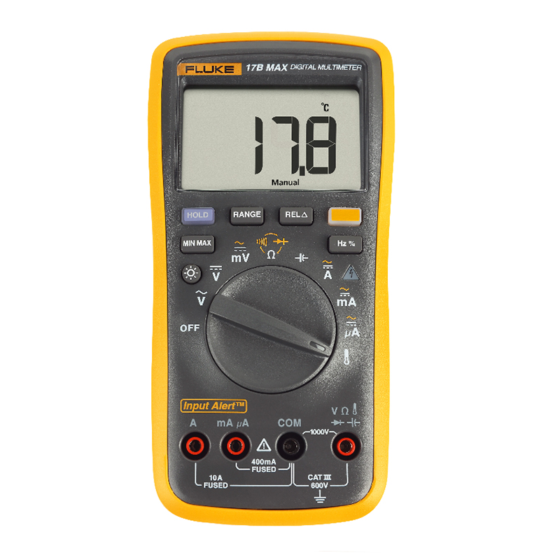

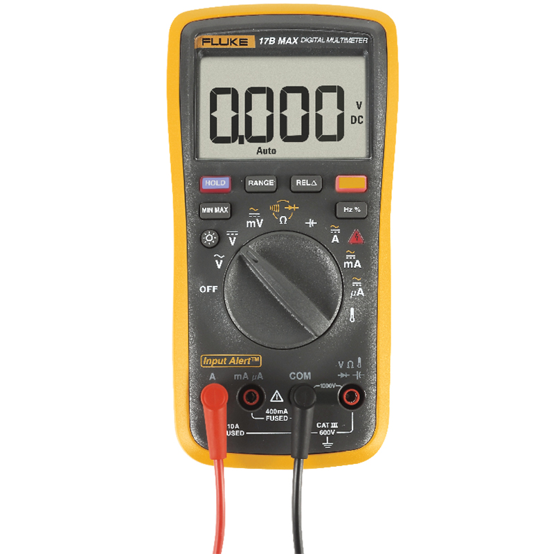
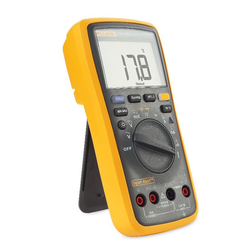
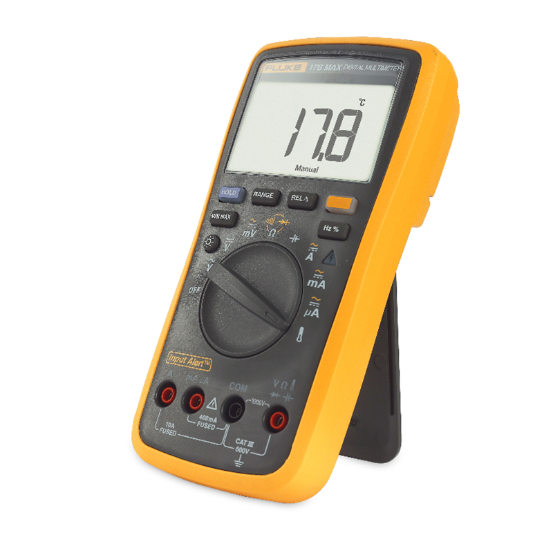
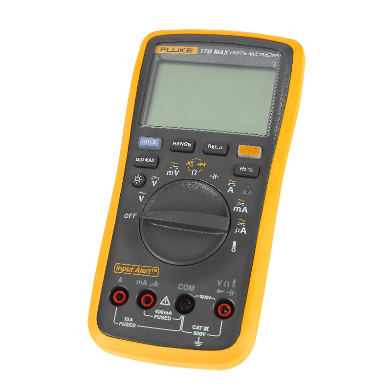


Product Overview: Fluke 17B MAX Digital Multimeter
The 17B MAX is an upgraded replacement model for the 17B+, which has been discontinued. The new multimeter has been upgraded with the following six features:
- New - Misoperation audible and visual alarms to avoid blowing fuses
- New - Standard with two pairs of regular & extra sharp pens for more scenarios (KIT model)
- New - Arbitrary key wake-up to improve testing efficiency
- NEW - Voltage readings upgraded to 6000 words
- New - Capacitance range upgraded to 2mF
- Added - Beeps increased

Misoperation audible and visual alarms Input Alert™
- Improve efficiency: Reduce the efficiency of field testing caused by misuse by frontline staff, and even safety accidents;
- Cost Savings: Fewer fuses to replace;
- Alarm effect by flashing lights in noisy and dark environments.
1mm Extra Tip Pen
- During board testing, the 1mm tip can accurately test to the device pins to avoid short circuits;
- The diameter of the meter pen is 20% thinner than the ordinary meter pen, which can be leaned closer to meet the needs of testing in a narrow space;
- Selected nib material, sturdy and durable, the meter pen has been rigorously tested, the nib is not easy to bend;
- The pen cap has a protective and anti-loss design;
- Only 02 and KIT models come standard with an extra-tip pen.

Wake up with any key
- No need to turn the knob to OFF to activate a dormant meter, making testing more efficient;
- Avoid dialing back into the wrong gear.
Product Specification: Fluke 17B MAX Digital Multimeter
| technical specification | ||||
|---|---|---|---|---|
| Accuracy is applicable for one year after calibration at operating temperatures from 18 °C to 28 °C and relative humidity from 0 % to 75 %. Accuracy specifications take the following form: ± ([% of reading] + [least significant digit word value]). | ||||
| functionality | range (of scales or measuring equipment) | resolution (of a photo) | accurate | |
| 15B MAX | 17B MAX | |||
| AC voltage (40 Hz to 500 Hz)1 | 6.000 V 60.00 V 600.0 V 1000 V |
0.001 V 0.01 V 0.1 V 1 V |
1.0 % + 3 | 1.0 % + 3 |
| AC Voltage (mV) | 600.0 mV | 0.1 mV | 3.0 % + 3 | 3.0 % + 3 |
| dc voltage | 6.000 V 60.00 V 600.0 V 1000 V |
0.001 V 0.01 V 0.1 V 1 V |
0.5 % + 3 | 0.5 % + 3 |
| DC voltage (mV) | 600.0 mV | 0.1 mV | 1.0 % + 10 | 1.0 % + 10 |
| AC current μA (40 Hz to 400 Hz)2 | 400.0 μA 4000 μA |
0.1 μA 1 μA |
1.5 % + 3 | 1.5 % + 3 |
| AC current mA (40 Hz to 400 Hz) 2 | 40.00 mA 400.0 mA |
0.01 mA 0.1 mA |
1.5 % + 3 | 1.5 % + 3 |
| AC current A (40 Hz to 400 Hz)2 | 4.000 A 10.00 A |
0.001 A 0.01 A |
1.5 % + 3 | 1.5 % + 3 |
| DC current μA 2 | 400.0 μA 4000 μA |
0.1 μA 1 μA |
1.5 % + 3 | 1.5 % + 3 |
| DC current mA 2 | 40.00 mA 400.0 mA |
0.01 mA 0.1 mA |
1.5 % + 3 | 1.5 % + 3 |
| DC current A 2 | 4.000 A 10.00 A |
0.001 A 0.01 A |
1.5 % + 3 | 1.5 % + 3 |
| Diode Testing 3 | 2.000 V | 0.001 V | 10% | 10% |
| Temperature 4 | 50.0 °C to 400.0 °C 0 °C to 50.0 °C -55.0 °C to 0 °C |
0.1 °C | inapplicable | 2 %+1 °C 2 °C 9 %+2 °C |
| Resistance (ohms) 5 | 400.0 Ω 4.000 kΩ 40.00 kΩ 400.0 kΩ 4.000 MΩ 40.00 MΩ |
0.1 Ω 0.001 kΩ 0.01 kΩ 0.1 kΩ 0.001 MΩ 0.01 MΩ |
0.5 % + 3 0.5 % + 2 0.5 % + 2 0.5 % + 2 0.5 % + 2 1.5 % + 3 |
0.5 % + 3 0.5 % + 2 0.5 % + 2 0.5 % + 2 0.5 % + 2 1.5 % + 3 |
| capacitors6 | 40.00 nF 400.0 nF 4.000 μF 40.00 μF 400.0 μF 2000 μF |
0.01 nF 0.1 nF 0.001 μF 0.01 μF 0.1 μF 1 μF |
2 % + 5 2 % + 5 5 % + 5 5 % + 5 5 % + 5 5 % + 5 |
2 % + 5 2 % + 5 5 % + 5 5 % + 5 5 % + 5 5 % + 5 |
| frequency1(10 Hz to 100 kHz) | 50.00 Hz 500.0 Hz 5.000 kHz 50.00 kHz 100.0 kHz |
0.01 Hz 0.1 Hz 0.001 kHz 0.01 kHz 0.1 kHz |
inapplicable | 0.1 % + 3 |
| duty cycle1 | 1% to 99% | 0.10% | inapplicable | 1 % Typical situation7 |
| Throughput Threshold | - | - | 70Ω | 70Ω |
| backlight | - | - | there are | there are |
| 1 All AC currents, frequencies, and duty cycles are specified from 1 % to 100 % of range. Input values below 1 % of range are not specified. 2 Typical load voltage DC/AC current µA: 100 µV / µA, DC/AC current mA: 2 mV/mA, DC/AC current A: 0.03 V/A 3 Typically, the open-circuit test voltage is 2.0 V and the short-circuit current <0.6 mA. 44 Type K thermocouple support 5 5 Typical open-circuit test voltage 0.54 V, maximum short-circuit current 1.8 mA 6Specifications do not include errors due to test lead capacitance and capacitive substrate (which can be as high as 1.5 nF in the 40 nF range). 7 Typical is a frequency of 50 Hz or 60 Hz and a duty cycle of 10 % to 90 %. |
||||
| Input Characteristics | ||||
|---|---|---|---|---|
| functionality | overload protection | Input Impedance (nominal) | Common mode rejection ratio | Conventional mode rejection ratio |
| alternating current | 1000 V 1 | >10 MΩ, <100 pF | Greater than 60 dB at 50 Hz or 60 Hz | - |
| AC Voltage (mV) | 1000 V 1 | >1 MΩ, <100 pF | Greater than 80 dB at 50 Hz or 60 Hz | - |
| dc voltage | 1000 V 1 | >10 MΩ, <100 pF | More than 100 dB at 50 Hz or 60 Hz | Greater than 60 dB at 50 Hz or 60 Hz |
| DC voltage (mV) | 1000 V 1 | >1 MΩ, <100 pF | Greater than 80 dB at 50 Hz or 60 Hz | - |
| 1106 V Hz (maximum) | ||||
| General technical indicators | |
| Maximum voltage between any terminal and ground | 600 V |
| Maximum differential voltage between V terminal and COM terminal | 1000V |
| Display (LCD) | 6000 counts, updated 3 times per second |
| Battery Type | 2 AA, IEC LR6 |
| Battery life | Minimum 500 hours |
| temp | Operating temperature: 0 °C to 40 °C; Storage temperature: -30 °C to 60 °C |
| relative humidity | Operating humidity: ≤ 90 % relative humidity at 10 °C to 30 °C; ≤ 75 % relative humidity at 30 °C to 40 °C; non-condensing (below 10 °C) |
| Operating Humidity, 40 MΩ Range | Relative humidity ≤ 80 % at 10 °C to 30 °C; Relative humidity ≤ 70 % at 30 °C to 40 °C. |
| height above sea level | Working altitude: 2000 m; storage: 12000 m |
| temperature coefficient | 0.1 X (specified accuracy)/°C (28 °C) |
| Fuse protection for current input | 440 mA, 1000 V fast-fusing, Fluke-specified parts only. 11 A, 1000 V Fast Fusing, Fluke Specified Parts Only |
| Volume (H x W x L) | 183 mm x 91 mm x 49.5 mm |
| weights | 455 g |
| IP rating | IP40 |
| safety | IEC 61010-1, IEC 61010-2-030 CAT III 600 V, pollution class 2 |
| electromagnetic environment | IEC 61326-1: Portability |
| electromagnetic compatibility | Only available in Korea |
Class A equipment (industrial broadcasting and communications equipment) 1
11This product complies with the requirements for industrial (Class A) electromagnetic wave equipment, and the seller or user should be aware of this. This equipment is intended for use in a work environment, not a home environment.
Model: Fluke 17B MAX Digital Multimeter
Fluke 17B MAX-01 Digital Multimeter
- TL75 Test Lancet with Two Protective Caps
- Type K Thermocouple Temperature Probes
- 2 AA batteries
- user manual
Fluke 17B MAX-02 Digital Multimeter
- TL31 Extra Tip Pen with Two Protective Caps
- Type K Thermocouple Temperature Probes
- user manual
Fluke 17B MAX KIT Digital Multimeter
- TL75 Test Lancet with Two Protective Caps
- TL31 Extra Tip Pen with Two Protective Caps
- Type K Thermocouple Temperature Probes
- 2 AA batteries
- user manual


