 Comprehensive test and measurement service provider-Shenzhen Weike Electronic Technology Co.
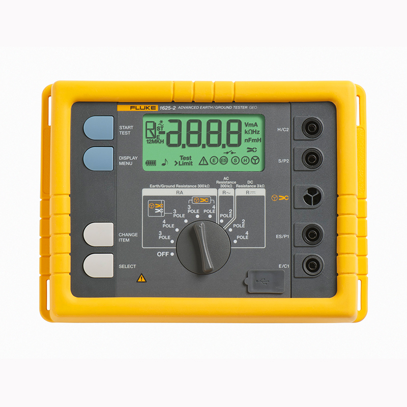
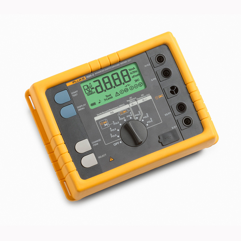


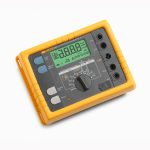


Product Overview: Fluke 1625-2 Ground Resistance Tester
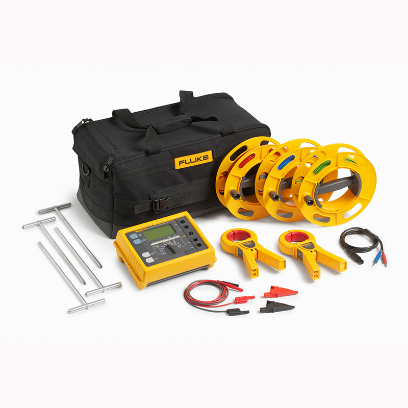
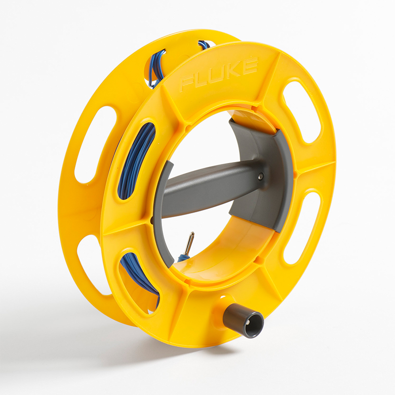
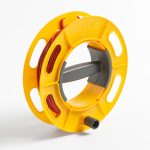
The Fluke 1625-2 Ground Resistance Tester is capable of storing and downloading data via a USB port. Best-in-class accessories help simplify and speed up testing time.
- Three-pole and four-pole potential drop ground resistance loop testing
- Quadrupole soil resistivity test
- Selective ground rod test using 1 jaw
- Stakeless ground rod test using 2 jaws
- IP56 protection for outdoor use
- Hard Carrying Case
- USB data storage and transfer
What's more, the tester is easy to use. With each test, the tester prompts you for the ground stake or jaws you need to use; a large rotary switch ensures that you can operate it even with gloves on.
Product Specification: Fluke 1625-2 Ground Resistance Tester
| General technical indicators | ||||
| memory (unit) | Access to up to 1500 records stored in internal memory via USB port | |||
| measurement function | Interference voltage and frequency, 3-pole and 4-pole earth resistance with/without clamp-on current transformers, 2-pole AC resistance, 2-pole and 4-pole DC resistance | |||
| monitor | 4 digits (2999 digits) - 7-segment LCD (improved visibility) | |||
| manipulate | Center rotary switch and function keys | |||
| temperature range | ||||
| operating temperature | -10 °C to 50 °C (14 °F to 122 °F) | |||
| storage temperature | -30 °C to 60 °C (-22 °F to 140 °F) | |||
| temperature coefficient | ± 0.1% /°C of reading 28 °C | |||
| Type of protection | Protection class IP56 for the housing and IP40 for the battery cover according to EN60529. | |||
| Maximum voltage | Warning - Socket "jaws" to socket E, ES, S or H | |||
| Urms = 0 V | ||||
| Sockets E, ES, S, or H in any combination with each other, max.rms = 250 V (misuse) | ||||
| safety | Protected by double and/or reinforced insulation. Max. 50 V to earth (according to IEC61010-1). Pollution class 2 | |||
| quality standard | Developed, designed and manufactured according to DIN ISO 9001 standards | |||
| influence of external fields | Conforms to DIN 43780 (8/76) | |||
| auxiliary power | 6 x 1.5 V alkaline batteries (IEC LR6 or AA type) | |||
| Battery life range | With IEC LR6/ AA types: typically 3,000 measurements (RE+RH ≤ 1 kΩ) | |||
| With IEC LR6/ AA types: typically 6,000 measurements (RE + RH > 10 kΩ) | ||||
| Dimensions (W x H x D) | 250 x 133 x 187 mm (9.75 x 5.25 x 7.35 in) | |||
| weights | ≤ 1.1 kg (2.43 lb) (without accessories); 7.6 kg (16.8 lb) (with accessories and battery in carrying case) | |||
| Housing Material | polyesters | |||
| Interference voltage DC + AC measurement (UST) | ||||
| Measurement error limits: methods | full-wave rectifier (FWR) | |||
| Measurement range | 1 V to 50 V | |||
| Display range | 0.0 V to 50 V | |||
| resolution (of a photo) | 0.1 V | |||
| frequency range | AC/DC 45 Hz to 400 Hz sine wave | |||
| accurate | ± (5% + 5 digits of reading) | |||
| measurement sequence | Approx. 4 measurements/second | |||
| internal resistance | Approx. 1.5 MΩ | |||
| Maximum overload | Urms = 250 V | |||
| Measurement of interference frequency (F) | ||||
| Measurement error limits: methods | Measurement of the oscillation period of the disturbance voltage | |||
| measuring range | 6.0 Hz to 400 Hz | |||
| Display range | 16.0 Hz to 299.9 Hz to 999 Hz | |||
| resolution (of a photo) | 0.1 Hz to 1 Hz | |||
| range (of scales or measuring equipment) | 1 V to 50 V | |||
| accurate | ± (1% + 2 digits of reading) | |||
| Ground resistance (RE) | ||||
| Measurement Methods | Measurement of current and voltage with probes according to IEC 61557-5 | |||
| open circuit voltage | 20/48 V, AC | |||
| short-circuit current | 250 mA (AC) | |||
| Measurement frequency | Manual or automatic selection of 94, 105, 111 and 128 Hz (AFC), in function R¹ 55 Hz | |||
| noise suppression | 120 dB (16 2/3, 50, 60 and 400 Hz) | |||
| Maximum overload to ground | Urms = 250 V | |||
| Electrical measurement specifications | ||||
| Inherent error or amount of influence | Terms of reference or designation of scope of work | Symbol Code | Required or tested according to the relevant parts of the IEC1557 standard. | Test Type |
| inherent error | reference condition | A | Part 5, section 6.1 | R |
| placement | Reference position ±90 ° | E1 | Part 1, section 4.2 | R |
| Supply Voltage | at the limit values specified by the manufacturer | E2 | Part 1, sections 4.2 and 4.3 | R |
| temp | 0 °C and 35 °C | E3 | Part 1, section 4.2 | T |
| Series Interference Voltage | See Sections 4.2 and 4.3. | E4 | Part 5, sections 4.2 and 4.3 | T |
| Probe and auxiliary grounding electrode resistance | 0 to 100 x RA but ≤ 50 kΩ | E5 | Part 5, section 4.3 | T |
| system frequency | 99% to 101% for nominal frequency | E7 | Part 5, section 4.3 | T |
| system voltage | 85% to 110% for nominal voltage | E8 | Part 5, section 4.3 | T |
| operating error | B = ±(|A| + 1,15 √E²)1 E²2 E²3 E²4 E²5 E²6 ) | Part 5, section 4.3 | R | |
| B[%] = ± B/base x 100%
A = inherent error |
||||
| measuring range | 0.020 Ω to 300 kΩ | |||
| Display range | 0.001 Ω to 2.999 Ω | |||
| 3.00 Ω to 29.99 Ω | ||||
| 30.0 Ω to 299.9 Ω | ||||
| 0.300 kΩ to 2.999 kΩ | ||||
| 3.00 kΩ to 29.99 kΩ | ||||
| 30.0 kΩ to 299.9 kΩ | ||||
| resolution (of a photo) | 0.001 Ω | |||
| 0.01 Ω | ||||
| 0.1 Ω | ||||
| 1 Ω | ||||
| 10 Ω | ||||
| 100 Ω | ||||
| accurate | ± (2% + 2 digits of reading) | |||
| operating error | ± (5% + 5 digits of reading) | |||
| measuring time | Typically 8 seconds for fixed frequencies, maximum 30 seconds with automatic frequency control, to complete all measured frequency cycles. | |||
| Additional errors due to resistance of the probe and auxiliary grounding electrode | RH(RS + 2000 Ω)/RE x 1.25 x 10⁻⁶% + 5 digits | |||
| RH and RS measurement error | At a fixed frequency it is usually RE + RS + RH 10% | |||
| Maximum Probe Resistance | ≤ 1 MΩ | |||
| Maximum auxiliary grounding electrode resistance | ≤ 1 MΩ | |||
| If the error is within the limits required by IEC61557-5, it is automatically checked. If conditions cause the measurement error after measuring the probe, auxiliary ground electrode and ground resistance to exceed 30%, the display will show a warning symbol and indicate that RS or RH is too high. |
||||
| The automatic switching of the measurement resolution depends on the auxiliary grounding electrode resistance RH | ||||
| Umeas = RH at 48 V | < 300 Ω | |||
| < 6 Ω | ||||
| < 60 Ω | ||||
| < 600 Ω | ||||
| Umeas = RH at 20 V | < 250 Ω | |||
| < 2.5 kΩ | ||||
| < 25 kΩ | ||||
| < 250 kΩ | ||||
| resolution (of a photo) | 1 mΩ | |||
| 10 mΩ | ||||
| 100 mΩ | ||||
| 1 Ω | ||||
| Selective earth resistance measurement (RE jaws) | ||||
| Measurement Methods | Measurement of currents and voltages with probes according to EN 61557-5 and measurement of currents in individual branch circuits with an additional transformer. | |||
| open circuit voltage | 20/48 V, AC | |||
| short-circuit current | 250 mA (AC) | |||
| Measurement frequency | Manual or automatic selection 94, 105, 111 and 128 Hz (AFC), 55 Hz (R¹) | |||
| noise suppression | 120 dB (162/3, 50, 60 and 400 Hz) | |||
| Maximum overload to ground | Maximum Urms = 250 V (measurement will not be initiated) | |||
| measuring range | 0.020 Ω to 300 kΩ | |||
| Display range | 0.001 Ω to 2.999 Ω | |||
| 3.00 Ω to 29.99 Ω | ||||
| 30.0 Ω to 299.9 Ω | ||||
| 0.300 kΩ to 2.999 kΩ | ||||
| 3.00 kΩ to 29.99 kΩ | ||||
| resolution (of a photo) | 0.001 Ω | |||
| 0.01 Ω | ||||
| 0.1 Ω | ||||
| 1 Ω | ||||
| 10 Ω | ||||
| accurate | ± (7% + 2 digits of reading) | |||
| operating error | ± (10% + 5 digits of reading) | |||
| Additional errors due to typical electrode resistance of the probe and auxiliary grounding | RH(RS + 2000 Ω)/RETOTAL x 1.25 x 10⁻⁶% + 5 digits | |||
| RH and RS measurement error | At a fixed frequency it is usually RETOTAL + RS + RH 10% | |||
| measuring time | Typically 8 seconds at a fixed frequency using automatic frequency control, maximum 30 seconds to complete all measured frequency cycles. | |||
| Minimum current of a single branch to be measured | 0.5 mA | Use of transformers (1000:1) | ||
| 0.1 mA | Use of transformers (200:1) | |||
| Maximum disturbance current through the transformer | 3 A | Use of transformers (1000:1) | ||
| 1. Use recommended current clamps/transformers. | ||||
| Resistance Measurement (R~) | ||||
| Measurement Methods | Measurement of current and voltage | |||
| measured voltage | 20 V AC, rectangular pulse | |||
| short-circuit current | > 250 mA (AC) | |||
| Measurement frequency | Manual or automatic selection of 94, 105, 111 and 128 Hz (AFC) | |||
| measuring range | 0.020 Ω to 300 kΩ | |||
| Display range | 0.001 Ω to 2.999 Ω | |||
| 3.00 Ω to 29.99 Ω | ||||
| 30.0 Ω to 299.9 Ω | ||||
| 300 Ω to 2999 Ω | ||||
| 3.00 kΩ to 29.99 kΩ | ||||
| 30.0 kΩ to 299.9 kΩ | ||||
| resolution (of a photo) | 0.001 Ω | |||
| 0.01 Ω | ||||
| 0.1 Ω | ||||
| 1 Ω | ||||
| 10 Ω | ||||
| 100 Ω | ||||
| accurate | ± (2% + 2 digits of reading) | |||
| operating error | ± (5% + 5 digits of reading) | |||
| measuring time | Usually 6 seconds | |||
| Maximum interference voltage | 24 V, measurement cannot be started beyond 24 V | |||
| Maximum overload | Urms Maximum value = 250 V | |||
| Resistance measurement (R DC) | ||||
| Measurement Methods | Current-voltage measurements according to IEC 61557-4 possible | |||
| measured voltage | DC 20 V | |||
| short-circuit current | 250 mA DC | |||
| Formula for measured values | For quadrupole measurements, the H, S, and ES leads can be extended without additional error. Resistance > 1 Ω in conductor E can lead to an additional error of 5m Ω/Ω. |
|||
| measuring range | 0.020 Ω to 300 kΩ | |||
| Display range | 0.001 Ω to 2.999 Ω | |||
| 3.00 Ω to 29.99 Ω | ||||
| 30.0 Ω to 299.9 Ω | ||||
| 300 Ω to 2999 Ω | ||||
| 3.0 kΩ to 29.99 kΩ | ||||
| 30.0 kΩ to 299.9 kΩ | ||||
| resolution (of a photo) | 0.001 Ω | |||
| 0.01 Ω | ||||
| 0.1 Ω | ||||
| 1 Ω | ||||
| 10 Ω | ||||
| 100 Ω | ||||
| accurate | ± (2% + 2 digits of reading) | |||
| operating error | ± (5% + 5 digits of reading) | |||
| measurement sequence | Approx. 2 measurements/second | |||
| measuring time | Typically 4 seconds, including polarity reversal (bipolar or quadrupolar) | |||
| Maximum interference voltage | DC or AC voltage ≤3 V, measurement cannot be started beyond 3 V | |||
| Maximum Sensitivity | 2 Henry | |||
| Maximum overload | Urms = 250 V | |||
| Compensation for measuring wire resistance (RK) | ||||
| In the function RE Triode, RE In the four-pole (jaws), R AC and R DC diodes, you can turn on the compensation for measuring the resistance of the wire (RK) | ||||
| Formula for measured values | Rdemonstrate = Rsurveying - Rreparation² | |||
| 2. The setpoint input value RK = 0.000 Ω is measured by adjusting the measurement to vary within the range of 0.000 to 29.99 Ω. | ||||
| Stakeless ground loop measurement (double jaw, stakeless) | ||||
| Switching gears | RA Quadrupole (Double Jaw, No Stake) | |||
| resolution (of a photo) | 0.001 Ω to 0.1 Ω | |||
| measuring range | 0.02 Ω to 199.9 Ω | |||
| accurate | ± (7% + 3 digits of reading) | |||
| operating error | ± (10% + 5 digits of reading) | |||
| measured voltage | Vm = 48 V AC (primary voltage) | |||
| Measurement frequency | 128 Hz | |||
| Noise Current (IEXT) | Maximum IEXT = 10 A (AC) (RA < 20 Ω) | |||
| Maximum IEXT = 2 A (AC) to ground (RA > 20 Ω) | ||||
| Measurement principle: Stake-free measurement of the resistance in a closed loop using two current transformers. Automatic range selection. The information about the measurement of the stakeless ground loop is valid only if the measurement is carried out with the recommended current clamp at the specified minimum distance. |
||||
Model: Fluke 1625-2 Ground Resistance Tester
Fluke 1625-2
Fluke 1625-2 GEO Earth Ground Tester
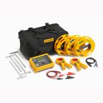
Included:
- Ground Tester
- user manual
- batteries
- Quick Reference Guide
- USB cable


