 Comprehensive test and measurement service provider-Shenzhen Weike Electronic Technology Co.
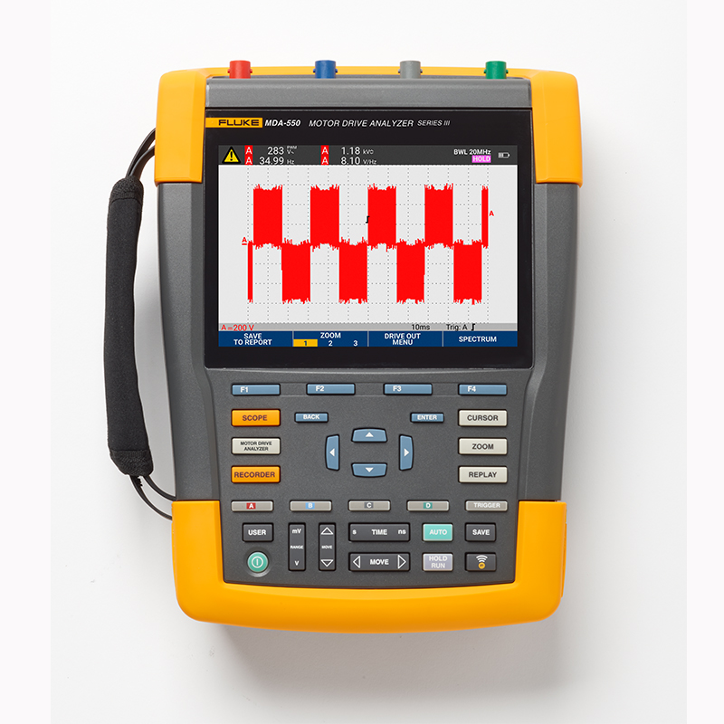


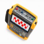


Product Overview: Fluke MDA-550 Series III Motor Drive Analyzer
Make motor drive troubleshooting simple with guided test setups and automated drive measurements that provide reliable, repeatable test results.
The Fluke MDA 550 Motor Drive Analyzer not only saves time and avoids the hassle of setting up complex measurements, it also simplifies motor drive troubleshooting. Simply select a test, and step-by-step guided measurements show you where you need to make voltage and current connections, while preset measurement configurations ensure that you capture all the data you need for each critical motor drive segment - from inputs to outputs, the DC bus, and the motor itself. From basic to advanced measurements, the MDA-550 has you covered, and with the built-in report generator, you can produce pre- and post-calibration reports quickly, easily, and confidently.
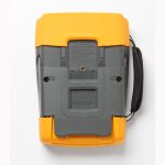
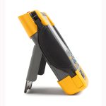
The MDA-550 is the ideal portable motor drive analysis and testing tool to help you safely identify and troubleshoot a wide range of common problems with motor inverter drive systems.
- Measuring the main parameters of a motor drive, including voltage, current, DC bus voltage levels and AC ripple, voltage and current imbalances and harmonics, voltage modulation and motor shaft voltage discharges.
- Perform extended harmonic measurements, to determine the impact of low and high harmonics on your power system.
- Perform guided measurementsUsing graphical step-by-step voltage and current connection diagrams, measurements are made on the motor driver input, DC bus, driver output, motor input, and motor shaft.
- Using a simplified measurement setupand preset measurement configurations that automatically trigger data collection based on the selected test program.
- Create reports quickly and easilyIt is especially good for keeping a troubleshooting log and collaborating with others.
- Measurement of additional electrical parametersThe newest addition to the range of products is a complete 500 MHz oscilloscope, meter and logging capability for comprehensive electrical and electronic measurements of industrial systems.
Fluke MDA-550 Motor Drive Analyzer Makes Analysis Easier Than Ever with Guided Test Measurements
Drive Input
By measuring the input voltage and current, and then comparing the nominal voltage rating of the drive to the actual voltage supplied, it is possible to quickly see if the values are within acceptable limits. Then, check the input current to determine if the current is within the maximum rating and if the wire gauge is appropriate. You can also check to see if the harmonic distortion is within acceptable levels by visually inspecting the waveform shape or by viewing the Harmonic Spectrum screen, which displays both total harmonic distortion and individual harmonics.
Voltage and current imbalance
Check the voltage imbalance on the input terminals to ensure that the phase imbalance is not too high (>6-8%) and that the phase rotation is correct. You can also check for current imbalance, as excessive imbalance may indicate a problem with the drive rectifier.
Extended Harmonic Measurement
Excessive harmonics are not only a threat to the safety of rotating machines, but also to other equipment connected to the electrical system. the MDA-550 is able to detect harmonics in motor drives, but also the possible effects of inverter switching electronics. the MDA-550 has three harmonic ranges, from the 1st to the 51st harmonic, from 1 to 9 kHz, and from 9 kHz to 150 kHz, and is able to detect any harmonic contamination problem. MDA-550
DC Bus
In a motor drive, the AC-DC conversion within the drive is critical, and for optimum drive performance it is essential that the voltage is correct, adequately filtered, and that ripple levels are kept low. High ripple voltages indicate a faulty capacitor or incorrect specification of the connected motor. The logging function can be used to dynamically check the performance of the DC bus in load-on operating mode.
drive output
When checking the drive output, focus on measuring the voltage-to-frequency (V/F) ratio and voltage modulation. When the V/F ratio measures high, the motor may be overheating. When the V/F ratio is low, the connected motor may not be able to provide the required torque on the load and thus not be able to adequately run the intended process.
voltage modulation
The measured value of the pulse width modulation signal is used to check for high voltage spikes that may cause damage to the insulation of the motor windings. The rise time or steepness of the pulse is indicated by the dV/dt reading (rate of change of voltage over time), which should be compared to the specified insulation value of the motor. These measurements can also be used to determine the switching frequency to determine if there is a potential problem with the electronic switching or grounding when the signal goes up and down.
Motor Input
Ensuring access to voltage for the motor input terminals is critical, as is proper selection of wiring between the drive and motor. Incorrect wiring choices can result in damage to the drive and motor due to excessive voltage spikes. It is important to check that the current at the terminals is within the motor's ratings, as high currents can cause the motor to overheat and therefore shorten the life of the stator insulation, leading to premature motor failure.
Motor shaft voltage
Voltage pulses from the variable speed drive may couple from the motor stator to the rotor, resulting in voltage across the rotor shaft. When this rotor shaft voltage exceeds the insulating capacity of the bearing grease, flashover currents (sparks) can occur, resulting in pitting and grooving of the motor's bearing races, which can lead to premature failure of the motor. the MDA-550 comes with a carbon fiber brush probe that easily detects the presence of damaging flashover currents, and pulse amplitude measurement and event counting features that allow you to take action before a failure occurs. faults before they occur. Adding this accessory allows you to detect potential damage without having to invest in an expensive, permanently installed solution.
Step-by-step guided measurements ensure you have the data you need when you need it.
The MDA-550 is designed to help you quickly and easily detect and troubleshoot a wide range of common problems with three-phase and single-phase motor inverter drive systems. With on-screen information and a step-by-step setup wizard, you can easily configure the analyzer and get the drive measurements you need to make better maintenance decisions quickly. From power inputs to installed motors, the measurements provided by the MDA-550 allow you to troubleshoot motor drives as quickly as possible.

Drive input step-by-step guided measurement connections

Drive output waveform with auto triggering

Extended harmonics spectrum from 9 kHz to 150 kHz

Voltage modulation with zoom

Product Specification: Fluke MDA-550 Series III Motor Drive Analyzer
| Measurement and analysis portfolio | |||||
| test point | subgroup | Readings 1 | Readings 2 | Readings 3 | Readings 4 |
| Motor Driver Input | |||||
| Voltage and current | |||||
| Phase - Phase | V-A-Hz | V ac+dc | A ac+dc | Hz | |
| V peak | V peak max | V peak min | V pk-to-pk | crest factor | |
| A peak | A peak max | A peak min | A pk-to-pk | crest factor | |
| Phase - Earth | V-A-Hz | V ac+dc | A ac+dc | Hz | |
| V peak | V peak max | V peak min | V pk-to-pk | crest factor | |
| A peak | A peak max | A peak min | A pk-to-pk | crest factor | |
| voltage imbalance | disequilibrium | V ac+dc | V ac+dc | V ac+dc | disequilibrium |
| peak value | V pk-to-pk | V pk-to-pk | V pk-to-pk | ||
| current imbalance | disequilibrium | A ac+dc | A ac+dc | A ac+dc | disequilibrium |
| peak value | A pk-to-pk | A pk-to-pk | A pk-to-pk | ||
| Motor Driver DC Bus | |||||
| direct current (D.C.) | V dc | V pk-to-pk | V peak max | ||
| corrugated | V ac | V pk-to-pk | Hz | ||
| Motor Driver Output | |||||
| Voltage and current (filtered) | V-A-Hz | V PWM | A ac+dc | Hz | V/Hz |
| V peak | V peak max | V peak min | V pk-to-pk | crest factor | |
| A peak | A peak max | A peak min | A pk-to-pk | crest factor | |
| voltage imbalance | disequilibrium | V PWM | V PWM | V PWM | disequilibrium |
| peak value | V pk-to-pk | V pk-to-pk | V pk-to-pk | ||
| current imbalance | disequilibrium | A ac+dc | A ac+dc | A ac+dc | disequilibrium |
| peak value | A pk-to-pk | A pk-to-pk | A pk-to-pk | ||
| voltage modulation | |||||
| Phase - Phase | Zoom 1 | V PWM | V pk-to-pk | Hz | V/Hz |
| Zoom 2 | V peak max | V peak min | Voltage increment | ||
| Peak Scaling 3 | V peak max | Voltage increment/s | peak rise time | overshoot | |
| Zoom 3 levels | Voltage increment | Voltage increment/s | Rise time level | overshoot | |
| Phase - Earth | Zoom 1 | V PWM | V pk-to-pk | V peak max | V peak min |
| Zoom 2 | V Peak max | V peak min | Voltage increment | Hz | |
| Peak Scaling 3 | V Peak max | Voltage increment/s | peak rise time | overshoot | |
| Zoom 3 levels | Voltage increment | Voltage increment/s | Rise time level | overshoot | |
| Phase-DC + | Zoom 1 | V PWM | V pk-to-pk | V Peak max | V peak min |
| Zoom 2 | V peak max | V peak min | Voltage increment | Hz | |
| Peak Scaling 3 | V peak max | Voltage increment/s | peak rise time | overshoot | |
| Zoom 3 levels | Voltage increment | Voltage increment/s | Rise time level | overshoot | |
| Phase-DC - | Zoom 1 | V PWM | V pk-to-pk | V peak max | V peak min |
| Zoom 2 | V peak max | V peak min | Voltage increment | Hz | |
| Peak Scaling 3 | V peak max | Voltage increment/s | peak rise time | overshoot | |
| Zoom 3 levels | Voltage increment | Voltage increment/s | Rise time level | overshoot | |
| Motor Input | |||||
| Voltage and current (filtered) | V-A-Hz | V PWM | A ac+dc | Hz | V/Hz |
| V peak | V peak max | V peak min | V pk-to-pk | crest factor | |
| A peak | A peak max | A peak min | A pk-to-pk | crest factor | |
| voltage imbalance | disequilibrium | V PWM | V PWM | V PWM | disequilibrium |
| peak value | V pk-to-pk | V pk-to-pk | V pk-to-pk | ||
| current imbalance | disequilibrium | A ac+dc | A ac+dc | A ac+dc | disequilibrium |
| peak value | A pk-to-pk | A pk-to-pk | A pk-to-pk | ||
| voltage modulation | |||||
| Phase - Phase | Zoom 1 | V PWM | V pk-to-pk | Hz | V/Hz |
| Zoom 2 | V peak max | V peak min | Voltage increment | ||
| Peak Scaling 3 | V peak max | Voltage increment/s | peak rise time | overshoot | |
| Zoom 3 levels | Voltage increment | Voltage increment/s | Rise time level | overshoot | |
| Phase - Earth | Zoom 1 | V PWM | V pk-to-pk | V peak max | V peak min |
| Zoom 2 | V peak max | V peak min | Voltage increment | Hz | |
| Peak Scaling 3 | V peak max | Voltage increment/s | peak rise time | overshoot | |
| Zoom 3 levels | Voltage increment | Voltage increment/s | Rise time level | overshoot | |
| motor shaft | |||||
| shaft voltage | Event closure | V pk-to-pk | |||
| Event Open | Voltage increment | Rise/fall time | Voltage increment/s | Events/second | |
| Motor Driver Inputs, Outputs and Motor Inputs | |||||
| harmonic (wave with frequency an integer multiple of the fundamental) | input voltage | V ac | V fundamental | Hz fundamental | % THD |
| amps | A ac | A fundamental | Hz fundamental | THD/TDD Percentage | |
| measurement function | norm |
| DC voltage (V dc) | |
| Maximum Voltage, 10:1 or 100:1 Probe | 1000 V |
| Maximum resolution with 10:1 or 100:1 probe (ground voltage) | 1mV/10mV |
| full scale reading | 999 counts |
| Accuracy at 4 s to 10 us/div | ± (1.5% + 6 counts) |
| True RMS voltage (V ac or V ac + dc) (when DC coupling function is selected) | |
| Maximum voltage (ground voltage) when using 10:1 or 100:1 probes | 1000 V |
| Maximum resolution when using 10:1 or 100:1 probes | 1 mv/10 mV |
| full scale reading | 999 counts |
| DC to 60 Hz | ± (1.5% + 10 counts) |
| 60 Hz to 20 kHz | ± (2.5% + 15 counts) |
| 20 kHz to 1 MHz | ± (5% + 20 counts) |
| 1 MHz to 25 MHz | ± (10% + 20 counts) |
| Pulse Width Modulation Voltage (V pwm) | |
| use | Measurement of pulse width modulated signals, e.g. motor drive inverter output signals |
| principle | The readings show the effective voltage based on the average of samples taken over the entire number of cycles of the fundamental frequency. |
| accurate | Same as Vac+dc for sine wave signals |
| Peak voltage (V peak) | |
| paradigm | Maximum peak, minimum peak, or inter-peak |
| Maximum voltage (ground voltage) when using 10:1 or 100:1 probes | 1000 V |
| Maximum resolution when using 10:1 or 100:1 probes | 10 mV |
| accurate | |
| Maximum Peak, Minimum Peak | ± 0.2 div |
| between peaks | ± 0.4 div |
| full scale reading | 800 counts |
| Current (AMP), using current clamps | |
| range (of scales or measuring equipment) | Same as V ac, Vac+dc or V peak |
| proportionality factor | 0.1 mV/A, 1 mV/A, 10 mV/A, 20 mV/A, 50 mV/A, 100 mV/A, 200 mV/A, 400 mV/A |
| accurate | Same as Vac, Vac+dc or V peak (plus current clamp accuracy) |
| Frequency (Hz) | |
| range (of scales or measuring equipment) | 1.000 Hz to 500 MHz |
| full scale reading | 9999 counts |
| accurate | ± (0.5% + 2 counts) |
| Voltage/Frequency Ratio (V/Hz) | |
| use | Displays the result of dividing the V PWM value (see V PWM) measured on the AC motor variable speed drive by the fundamental frequency. |
| accurate | % Vrms + % Hz |
| Voltage Imbalance Driver Input | |
| use | Displays the highest difference in percentage of a phase voltage divided by the average of the 3 true RMS voltages |
| accurate | Indicative percentage based on Vac+dc values |
| Voltage Imbalance Drive Output and Motor Input | |
| use | Displays the highest difference in percentage of a phase voltage divided by the average of 3 pulse width modulated voltages |
| accurate | Indicative percentage based on V PWM values |
| Current Imbalance Driver Input | |
| use | Displays the highest difference in percentage of a phase current divided by the average of 3 AC current values |
| accurate | Indicative percentage based on Aac+dc values |
| Current Imbalance Drive Output and Motor Input | |
| use | Displays the highest difference in percentage of a phase current divided by the average of 3 AC current values |
| accurate | Indicative percentages based on A ac values |
| Rise time and fall time | |
| readings | Difference in voltage (dV), difference in time (dt), difference in voltage divided by difference in time (dV/dT), overshoot |
| accurate | Same accuracy as oscilloscope |
| Harmonics and spectrum | |
| harmonic (wave with frequency an integer multiple of the fundamental) | DC to 51 times |
| spectral range | 1...9 kHz, 9-150 kHz (20 MHz filter on), to 500 MHz (voltage modulation) |
| shaft voltage | |
| Events/second | Indicative percentage based on rise and fall time (pulse discharge) measurements |
| Reporting data collection | |
| Number of screens | Typical 50 pages of screens can be saved in the report (depending on compression ratio) |
| transfer to computer | Use a 32 GB or smaller 2 GB USB flash drive or mini-USB to USB cable or WiFi connectivity and FlukeView™ 2 for ScopeMeter®. |
| Probe Settings | |
| Voltage Probe | 1:1, 10:1, 100:1, 1000:1, 20:1, 200:1 |
| current clamp | 0.1 mV/A, 1 mV/A, 10 mV/A, 20 mV/A, 50 mV/A, 100 mV/A, 200 mV/A, 400 mV/A |
| Axial Voltage Probe | 1:1, 10:1, 100:1 |
| safety | |
| General Information | IEC 61010-1: Contamination class 2 |
| surveying | Measurement standard IEC 61010-2-030: CAT IV 600 V/CAT III 1000 V |
| Maximum voltage between any terminal and the earth terminal | 1000 V |
| Maximum Input Voltage | Via VPS410-II or VPS421 1000 V CAT III/600 V CAT IV |
| BNC Input | A, B, C, D Direct 300 V CAT IV |
| Maximum float voltage, using test tool or test tool with VPS410-II/VPS421 voltage probe | 1000 V CAT III/600 V CAT IV from any terminal to ground; 1000 V CAT III/600 V CAT IV between any terminals |
| Operating voltage between probe tip and probe reference lead | VPS410-II: 1000 V VPS421: 2000 V |
Model: Fluke MDA-550 Series III Motor Drive Analyzer
Fluke MDA-550 Series III Motor Drive Analyzer
Attached:
- 1 BP 291 lithium ion battery pack
- 1 x BC190 Charger/Power Adapter
- 3 VPS421 100:1 High Pressure Probes with Alligator Clips
- 1 VPS410-II-R 10:1 500MHz Voltage Probe
- 3 i400s AC Current Clamps
- 1 SVS-500 Axis Voltage Measurement Kit (3 brushes)
- probe holder
- Two-piece extension bar and magnetic holder
- Large Protective Carrying Case with Wheels (C437-II)
- FlukeView-2 PC Software (Full Version)
- WiFi Adapter

