 Comprehensive test and measurement service provider-Shenzhen Weike Electronic Technology Co.
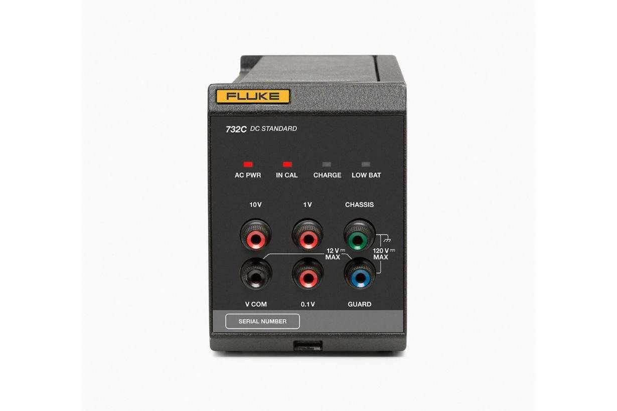


Product Overview: 732C and 734C DC Voltage Reference Standards
Accurate, stable 10 V reference in your lab
With the 734C, establishing and maintaining the primary voltage standardizer in your laboratory is simple. Over time, you can reduce the uncertainty of the 734C by a factor of three by making frequent comparisons of the four units and by performing periodic calibrations of one or more of the units.
From 1984 until the acquisition of our Josephson Array, Fluke Calibration's primary standards laboratory maintained its corporate voltages in such a way as to reduce absolute uncertainty to ± 0.35 µV/V, traceable to national standards.
734C Supports 1 V and 0.1 V
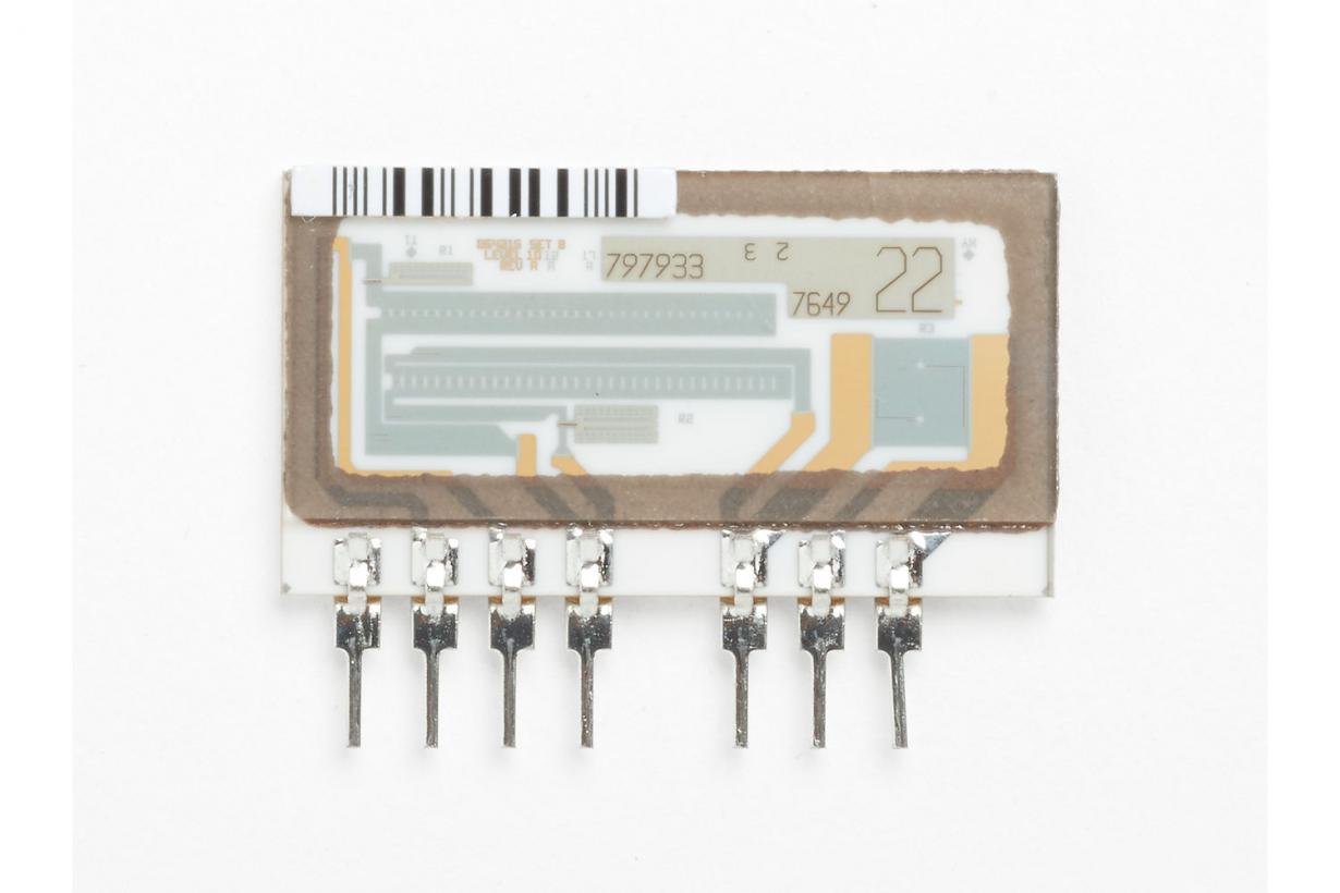
1 V and 0.1 V are the primary calibration/verification points for digital multimeters. Thanks to a network of high-precision thin-film resistors (manufactured in Fluke's own thin-film factory facility), the 734C now comes standard with these two additional outputs. No external separator is required, making measurement setup easier and less likely to go wrong.
Selected models for demanding applications
Fluke Calibration offers select models for customers who need primary standards lab capabilities to calibrate demanding workloads and to independently send standards to other labs for calibration. The calibration process is the same for the Basic and Select models. The only exception is that the Select models (732C/S/C or 734C/S/04) are compared to the Fluke Calibration J-array for 180 days of drift characterization data and provide up to twice the stability at 10 V. This process ensures that the standard selected meets the stringent drift requirements of the standard lab. This process ensures that the best possible standard is selected to meet the stringent drift performance requirements.
Supporting your traceability requirements
Fluke Calibration provides the products and services you need to manage your traceability requirements Fluke Calibration performs an output voltage calibration on a new 732C by comparing the new 732C to its own factory maintained J-array. The base model 732C is shipped cold ("unpowered") and is accompanied by a Certificate of Failure to Calibrate attesting to its operability. The owner is responsible for providing traceability to local requirements.
The 732C unit with approved calibration and drift characteristic data is shipped "hot" (energized) when ordered. During manufacture, each 732C is compared to a Fluke Calibration direct voltage standard for at least 90 days to obtain drift characteristic data. Once the drift rate is known, the projected output voltage for December is determined. The unit is then shipped under power. The continuous power condition needs to remain active from the time of shipment until delivery to the laboratory. If continuous power cannot be maintained, the validity of the calibration may be significantly reduced. Contact your Fluke Calibration representative to determine if a 732C Replacement is available in your area.
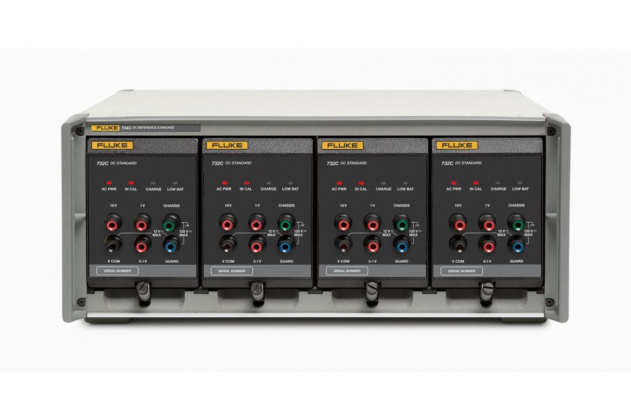
Why use a four-device reference?
The Four Unit Voltage Reference Standard is great for any situation where you need to maintain and pass on a reference voltage. At least three units are compared to each other in order to detect and recognize variations in the output of any one unit. The fourth unit may be used as a backup or for delivering voltage to and from a remote location. When it is returned to the laboratory, it may be compared to the other three units in order to determine whether its output has drifted during transportation.
But a four-device reference is not just that simple. According to NBS Technical Note 1239, published by the National Bureau of Standards (now NIST) in 1987, four to six references are required to provide measurement integrity and redundancy, as well as to minimize the number of measurements required. The references must be completely independent of each other. Otherwise, common elements such as power supplies or ovens may affect the correlation of the reference outputs. In addition, by utilizing frequent intercomparisons of the four units, you can detect at what point any one unit begins to drift out of specification or needs to be repaired.
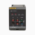
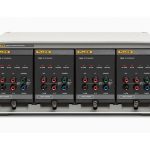
Each 732C is a self-contained DC standard with its own power supply, oven, auxiliary electronics and packaging. Each unit can be purchased individually or as a complete 734C system, which consists of four 732Cs that slide into a rack-width enclosure.
Why should you choose the 732C or 734C?
- Independent. The 734C can be supplied with fully mechanically and electrically independent standardizers for each of its four standardizers.
- Portability. Each 732C standard is designed with portability in mind. Each unit is small, lightweight, rugged and has a long battery run time.
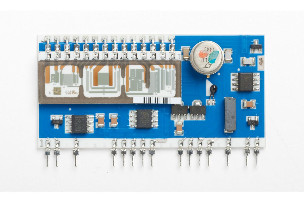
- Confidence. The 732C is based on the proven Fluke Calibration 732A and 732B technologies. 732A is the widely recognized standard laboratory quality electronic reference for use in place of saturated standard units. Originally designed to transfer voltages within Fluke to production sites, it is now used worldwide in a variety of applications: from maintaining reference standards for research organizations to transferring voltage values from national laboratories or privately owned 10 V Josephson arrays.
Ideal support for pseudo-differential calibration
together with 742ACombined with the 742A-10k impedance standard, a single 732C makes a tough and compact pseudo-differential calibration support package for the Fluke 5730A high-performance multifunction calibrator and the Fluke 8508A reference multimeter, including the older generation 5700A and 5720A models.
Bring your reference to the workload
The work of the standards lab has changed. In the past, people brought their workloads to the standards lab. Today, the functions of the standards lab are distributed, requiring many calibrations to be performed in the field.The 734C and its electrically and mechanically independent 732C standardizer are designed to meet this need. The voltage reference in your lab remains undisturbed while you distribute voltages to remote locations outside the lab. When the unit is returned to the lab, it can be compared to the reference to determine if drift occurred during delivery. To maintain traceability to national standards, a unit may be transported to a national laboratory or other major standards laboratory for calibration, which still does not disturb the reference. Each 732C standardizer is relatively lightweight, weighing only 5.9 kg, and its 72-hour battery life provides ample capacity for extended transportation. An optional external battery extends capacity to 210 hours. A special shipping case for one 732C and an external battery further simplifies transportation.
The 732C is extremely rugged. The outputs can be shorted indefinitely, and the 10 V outputs can withstand currents up to 1100 VDC at 25 mA without destroying the unit or affecting its output.
Fluke's Service Options
Fluke offers two service options: For existing Fluke 732A, 732B, or 732C or similar DC reference standards already in service, Fluke Calibration can provide calibration certificates for these standards using the Direct Voltage Maintenance Program service. This service includes two calibration options that can be utilized depending on your needs.
Calibration done by Fluke Calibration
Voltage Reference Standards returned to a Fluke Calibration service facility can be easily serviced with a Calibration Certificate. Contact your Fluke Calibration representative or your local Fluke Service Center for more information on these calibration certificate options.
Calibration in your laboratory
With the Direct Voltage Maintenance Program (DVMP) 732C-200 service, we send Fluke Calibration-owned and calibrated voltage reference standards, including all necessary connecting cables and operating instructions, to your premises for comparison with one or more of your own reference standards. You obtain a series of readings within a few days and forward the standard(s) to the Fluke Calibration Standards Laboratory. A value associated with the Fluke standard is assigned for your reference. A preliminary calibration report will be sent back to you within a week. Once the standard is returned to Fluke Calibration, we compare it to the Fluke voltage reference standard. Assign final values for your reference and send you a final calibration report.732C-200 Service provides a calibration certificate for one local standard.
Notes: DVMP is not available in all areas. Contact your local Fluke sales representative for details.
Product Specifications: 732C and 734C DC Voltage Reference Standards
General technical indicators
| Table 1. | ||
| The line voltages shown in Table 1 are acceptable. The AC line current at 120 V AC is typically 0.13 A. Table 1. | ||
| 732C Line Voltage Setting | Accepted line voltage | Frequency of acceptance |
| 100 V | 90 V to 110 V | 50 Hz/60 Hz |
| 120 V | 108 V to 132 V | 50 Hz/60 Hz |
| 220 V | 198 V to 242 V | 50 Hz/60 Hz |
| 240 V | 216 V to 264 V | 50 Hz/60 Hz |
| norm | ||
| batteries | Battery operation | When fully charged, the internal battery will allow the product to operate for at least 72 hours at 23 ±5 °C, drawing a total current of 0 mA to 0.1 mA at output. |
| charging time | <36 hours with separate automatic battery charger | |
| External DC input | The rear panel input is used to power the product indefinitely from 12 V DC to 15 V DC. The DC power rating must be ≥300 mA. | |
| incommunicado | Resistance >10 000 MΩ from any terminal of the product to ground (chassis) or to AC line power is shunted at <1000 pF. | |
| Protection and grounding terminals | Enclosure ground connections are provided at the front and rear panels. Access to the internal guard is provided through the front panel terminal block. | |
| output protection | All outputs can be shorted indefinitely without damaging the product.10 V outputs can withstand other supply voltages as follows:
|
|
| Environmental requirements | |
| Specify the run | Temperature range: 15 °C to 35 °C |
| Relative humidity: 0 % to 90 % at 28 °C, up to 80 % at 35 °C, up to 50 % at 50 °C, non-condensing | |
| Altitude: 0 m to 1830 m (0 ft to 6000 ft) | |
| Unspecified runs | Temperature range: 0 °C to 50 °C |
| Relative Humidity: 0% to 90%, non-condensing | |
| Altitude: 0 m to 3050 m (0 ft to 10 000 ft) | |
| Storage (remove battery) | Temperature range: -40 °C to 50 °C |
| Relative humidity: non-condensing | |
| Altitude: 0 m to 12 200 m (0 ft to 40 000 ft) | |
| electromagnetic compatibility | |
| (EMC) The product operates in a standard laboratory environment where the radio frequency (RF) environment is highly controlled. | |
| international standard | IEC 61326-2-1; CISPR 11: Group 1, Class A controlled electromagnetic environments
Group 1 equipment intentionally generates and/or uses on-coupled RF energy, which is necessary for the internal operation of the equipment itself. Class A equipment is suitable for non-domestic use and in any equipment not directly connected to the low voltage network supplying residential buildings. This device, when connected to a test object, may generate emissions in excess of the levels specified in CISPR 11. This device may not meet the immunity requirements of 61326-1 when test leads and/or test probes are connected. |
| United States (FCC) | 47 CFR 15 Subpart B. This product is considered tax-exempt equipment under Section 15.103. |
| Korea (KCC) | Class A equipment (industrial broadcasting and communications equipment)This product complies with the requirements for industrial (Class A) electromagnetic wave equipment, and the seller or user should be aware of this. This equipment is intended for use in a commercial environment and not in a home environment. |
| safety | |
| safety | IEC 61010-1, installation category II, pollution class 2 |
| protection class | IEC 60529: IP20 |
| Mechanical specifications | ||
| 734C Dimensions | 732C and 732C-7001 Dimensions | |
| high degree | 17.8 cm (7.0 in) | 13.4 cm (5.28 in) |
| height | 43.2 cm (17.0 in) | 9.8 cm (3.85 in) |
| (of a speech etc) profundity | 50.3 cm (19.8 in) including handle | 40.6 cm (16.0 in) |
| weights | 30.4 kg (67 lb) | 5.91 kg (13 lb) |
| Performance specifications | |||
| output voltage | 10 V, 1 V, and 0.1 V are provided on separate terminals from the reference VCOM terminal block. | ||
| stability | The stability specifications for the 732C output with Tcal ±1 °C and the IN CAL indicator on are shown in Table 2. | ||
| Table 2. Standardizer Stability | |||
| output voltage | Stability (± µV/V) | ||
| 30 days | 90 days | 1 year | |
| 10 V | 0.3 | 0.8 | 2.0 |
| 1 V | 0.6 | 1.2 | 3.0 |
| 0.1 V | 1.2 | 2.9 | 9.8 |
| Table 3. Selection Stability | |||
| output voltage | Stability (±) µV/V) | ||
| 30 days | 90 days | 1 year | |
| 10 V | 0.3 | 0.8 | 1.0 |
| 1 V | 0.6 | 1.2 | 2.5 |
| 0.1 V | 1.2 | 2.9 | 8.0 |
| Output terminal noise | Specify output noise for daily and short-term observations at k=1. | ||
| Table 4. Output Terminal Noise | |||
| output voltage | S 1 (±µV/V) [1] | Sra (±µV/V) [2] | Noise (0.01 Hz to 10 Hz) (±µV/V rms) |
| 10V | 0.07 | 0.05 | 0.06 |
| 1 V | 0.16 | 0.14 | 0.15 |
| 0.1V | 1.4 | 1.3 | 1.0 |
| [1] S1 is the standard deviation of a 90-day regression (SDEV) on data from at least two stability tests per day. [2] Sra is the SDEV of the stability test data obtained using a 7-day sliding average filter (MAF). | |||
| For better performance, use this product in a controlled environment with good system grounding and shielding practices. For radiated EMI fields from 0.25 to 1 V/m and from 80 to 130 MHz, add 9 μV for the 1 V output and 3.6 μV for the 0.1 V output. For 1 V/m AC conducted EMI from 75 to 80 MHz, add 1 μV for the 1 V output and 0.7 μV for the 0.1 V output. 10 V outputs are generally unaffected by EMI fields up to 1 V/m or conducted EMI up to 1 Vrms. The 10 V output is typically unaffected by EMI fields up to 1 V/m or conducted EMI up to 1 Vrms. | |||
| Table 5. Output Current and Impedance | ||
| output voltage | Output Current Limit | Output Impedance |
| 10V | 12mA [1] | ≤1mΩ |
| 1V | 1.2mA [1] | ≤1mΩ |
| 100mV | 20pA | ≤100Ω |
| [1] Limit the total output current to ≤0.1 mA to achieve the specified battery operating condition. | ||
| Table 6. Return (Hysteresis) Errors | |
| Table 6 shows the change in the 10V output voltage after a power failure (battery off) and a constant temperature in the range of 23 °C to 35 °C. The output voltage is the same as the output voltage of the battery. | |
| Power off time | 10 V change in output value (± μV/V) |
| ≤10 minutes | 0.1 |
| 10 minutes to 24 hours | 0.25 |
| 24 hours to 14 days | 0.25 |
| Stabilization time requirements | |
| Warm-up time required after AC line and battery power is turned off. the IN CAL indicator will turn off and recalibration will be required. The previously specified return error specification may be used in the event of a power outage. | |
| No power interruption | No stabilization time is required after the product is moved to another environment. |
| Power off <1 hour | Requires 1 hour to warm up |
| Power off >1 hour | Requires 24 hours to warm up |
| Table 7. Temperature Coefficients | |
| From 15 °C to 35 °C, the temperature coefficients relate to the information in Table 7. | |
| output voltage | Temperature Coefficient (± μV/V per V/°C) |
| 10 V | 0.04 |
| 1 V | 0.1 |
| 0.1 V | 0.2 |
| Table 8. Output and Elevation | |
| If the calibration elevation changes, the output voltage change relates to the information in Table 8. | |
| output voltage | Output Variation (± μV/V per 1000 feet) |
| 10 V | 0.05 |
| 1 V | 0.09 |
| 0.1 V | 0.18 |
| Load Adjustment | |
| 10V Output Load Variation | Maximum 10V output variation (± mV/V) |
| 0 mA to 12 mA (no load to full load) | 1 |
| 0 mA to 2 mA | 0.1 |
| Power Adjustment |
| The output does not vary more than 0.05 μV/V for any 10% line voltage change or for the full operating range of the battery. |
Model: 732C and 734C DC Voltage Reference Standards
732C
10V DC voltage reference standard
732C/C
10V DC Reference Standard + Characterization Data (Powered Transportation - INTL)
732C/S/C
Selected 10 VDC Reference Standards + Characterization Data (Powered Transportation - INTL)
734C
Base Model 4 Cell DC Reference Standard (ships cold)
734C/04
4 Unit DC Reference Standard + 4 Characterization (shipped in hot form - INTL)
734C/S/04
Selected 4-unit DC reference standard + 4 sets of characterization data (electrified transport)


