 Comprehensive test and measurement service provider-Shenzhen Weike Electronic Technology Co.
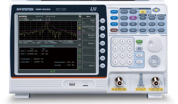


The GSP-9330 is a spectrum analyzer for high-speed testing at 3.25 GHz, with a fastest scan speed of 204 uS. Users can easily process and analyze modulated signals with the fast scan time. The key to modulated signal processing is the fast scan time and signal demodulation function. In addition to analog AM/FM demodulation and analysis functions, the GSP-9330 also provides demodulation and analysis functions for ASK/FSK and 2FSK digital signals. Today, the issue of EMC is critical to the product design process. Therefore, the GSP-9330 incorporates an EMC prediction solution to facilitate EMC testing. the GSP-9330's easy EMC prediction process dramatically reduces the time to product release for users.
A. Fast signal scanning
Speed is an important specification for spectrum analyzers, and the GSP-9330 offers scanning speeds of up to 204us. The fast scan time allows the user to identify and analyze a variety of fast or transient signals. Such as frequency/AM signals, Bluetooth frequency hopping signals, tuned voltage controlled oscillators or other interference signals in the ISM band.
FM Signal Monitoring Taiwan 3G Telecom Signal
B. Modulated signal analysis
2FSK modulation is widely used in low power and low data rate RF communication applications because of its low design cost and low power consumption. Today, 2FSK modulation technology is used in a wide variety of products and systems such as consumer electronics, automotive electronics, RFID, automatic meter reading and industrial control devices, etc. 2FSK analyzer can measure parameters such as Carrier Power, FSK Bias, Carrier Frequency & Carrier Frequency Offset measurements. Users can set the judgment conditions on the frequency deviation and carrier offset to quickly determine the test results.
RFID and optical communication systems often use Amplitude Shift Keying (ASK), while wireless phones, paging systems and RFID and many other applications use Frequency Shift Keying (FSK). ASK/FSK demodulates and analyzes the measured parameters, including amplitude depth, frequency offset, carrier power and carrier frequency shift, symbol code and waveform. The parameters measured for ASK/FSK demodulation and analysis include AM depth, frequency offset, carrier power and carrier frequency offset, symbol code and waveform. User can set pass/fail test results for AM depth, frequency offset, carrier power and carrier offset. It also provides preamble & sync function for data message.
AM/FM signal analysis measurement parameters, including AM depth, frequency deviation, modulation rate, carrier power, carrier frequency offset, and SINAD.Users can set the judgment conditions for AM depth, frequency deviation, carrier power, and carrier offset for quick test results.AM/FM demodulation function can demodulate and listen to AM or FM broadcast signals.
2FSK signal analysis ASK/FSK signal analysis and demodulation function AM/FM signal analysis and demodulation function
C. EMC Pre-Diagnostic Test Solutions
The GSP-9330 has built-in EMI 200/9k/120k/1MHz filters, 20dB low-noise amplifiers, and Quasi-Peak/Average detector modes. Users can perform the required tests in the EMC Pretest function of the machine, and can also use it with kits for radiated and conducted tests.
The GKT-008 provides a complete set of near-field rods to simplify complex measurements and simulate 3m/10m far-field tests in the lab, saving engineers' time and cost for debugging and traveling to and from the lab; and it can be paired with the Tracking Generator function of the GSP-9330 to perform EMS tests.
For the conductivity test, LISN and Isolated Transformer can be used to measure the electromagnetic conductivity. If you are worried about the voltage fluctuation of the test terminal is large or complicated, Transient Limiter can be used to make the test equipment more secure.
Spectrum Analyzer is the English word for Spectrum Analyzer.Abbreviation: SpectrometerThe
Spectrum Analyzer Principle
Broadly speaking, the signal spectrum is the total set of all frequency components that make up the signal; narrowly speaking, the amplitude spectrum that varies with frequency is often referred to as the spectrum in general spectrum measurements.
Spectral Measurement: Measurement of each frequency component of a signal in the frequency domain to obtain multiple parameters of the signal.
The main parameters of the spectrum analyzer
The main parameters of the spectrum analyzer are listed below:
Frequency indicators: input frequency range, frequency sweep width, frequency resolution, frequency accuracy, andaging rate, Resolution Bandwidth, Display Bandwidth
Amplitude metrics: amplitude measurement accuracy, dynamic range.Phase Noise, 底噪,1dB压缩点,最大输入电平, Attenuator, Preamplifier
Spectrum Analyzer Usage
A spectrum analyzer is a widely used measurement instrument in wireless communication equipment, component and system measurement applications. It measures and presents the frequency distribution of RF signals. Messages such as frequency and amplitude of the signal can be measured and read by a spectrum analyzer. Spectrum analyzer has a wide range of applications, it can be used for remote control testing, Bluetooth testing, EMC EMC testing (conducted/radiated), P1dB testing, amplifier testing, filter testing, cell phone repair testing, wire loss testing, repeater testing, and so on.
Goodwell Electronics officially entered the RF field in 1999, and has been rapidly developing its products over the decades, with the current product range of 1GHz-3.25GHz. Goodwell designed spectrum analyzer, test speed is extremely fast, ultra-fast scanning time, rich signal demodulation functions, and the introduction of EMI / EMC Pretest function integration, so that the test EMI / EMC faster.
Modulated signal analysis and demodulation
Goodwell electronic spectrum analyzer with powerful modulation signal analysis and demodulation functions. The analyzer is equipped with AM (Amplitude Modulation), FM (Frequency Modulation), ASK (Amplitude Shift Keying), FSK (frequency shift keying) analysis demodulation function.
Electromagnetic compatibility (EMC) use
The EMI/EMC Pretest test program can detect EMI/EMC problems at the initial stage and deal with them in a timely manner, which helps to accelerate the time-to-market.
Radiation test kit GKT-008 provides a complete combination of near-field probes, which can simplify complex measurements and simulate the laboratory's 3m/10m far-field test, significantly saving engineers debugging and traveling to and from the laboratory time and cost; you can also use GKT-008 with the Tracking Generator function of the GSP-9330 to conduct EMS testing.
Conductivity testing can be performed with a Line Impedance Stabilization Network (LISN) and an Isolated Transformer for electromagnetic conduction measurements.When debugging with contact probes is required, ifIf you are concerned about large or complex voltage variations at the test terminal, you can use a pulse limiter to make the test equipment safer.
GSP Series:The GSP series spectrum analyzers are equipped with flexible and convenient functions, user-friendly operation panels, and complete setup menus for a wide range of applications in experiments, measurements, and maintenance services.The GSP series shows remarkable achievements in Goodwell's design technology. There are many features designed to perform high stability measurements, further signal analysis and high performance measurements. The adopted full temperature frequency stabilization, integrated efficient heat dissipation mechanism, stability maintenance, and accurate measurement. Topographic and spectrogram display modes were developed to interpret signals in color temperature patterns to perform signal persistence and timing. SEM, ACPR, OCBW, CNR, CTB, CSO measurements, marker frequency counter and many other measurement functions are also provided. Sequence functions allow a series of measurement steps to be created and performed without the need to connect to. Common ports included are included in the remote control design.
Need a product description? Please contact Mr. Jianjun Huang: Tel: 0512-66617177 ext. 697 E-mail: jianjun_16@instek.com.cn
EMC Program 1 https://v.youku.com/v_show/id_XNTE2NjAwMTY4OA==.htmlEMC Program 2 https://v.youku.com/v_show/id_XNTE2NjAwMTY5Mg==.htmlEMC Program 3https://v.youku.com/v_show/id_XNTE2NjAwMTY4NA==.htmlEMC Program 4https://v.youku.com/v_show/id_XNTE2NjAwMTgwNA==.html电池兼容方案6https://v.youku.com/v_show/id_XNTE2NjAwMTgwMA==.html
Quick Selection
| model number | frequency range | functionality | display mode | scanning time | Standard Interface |
| GSP-9330 | 9KHz-3.25GHz | EMI,P1dB,AM,FM,ASK,FSK,2FSK | Spectrum, Topology, Spectrum | 204us | USB/RS232 |
| GSP-9300B | 9KHz-3GHz | P1dB | Spectrum, Topology, Spectrum | 204us | USB/RS232 |
| GSP-730 | 150KHz-3GHz | 30KHz, 100KHz, 300KHz, 1MHz | spectrogram | 300ms | USB/RS232 |
| GSP-818 | 9KHz-1.8GHz | 10Hz-500KHz in 1-10 steps | spectrogram | 10ms | USB/LAN |
| Detailed specifications | ||
| frequency | ||
| frequency | ||
| realm | 9 kHz ~ 3.25 GHz | |
| Setting resolution | 1 Hz | |
| frequency reference source | ||
| accuracy | ±[(final tuning cycle x aging rate) + stability of temperature + stability of voltage supply | |
| aging rate | ±1 ppm max. | After 1 year of tuning |
| Stability of temperature | ±0.025 ppm | 0~ 50 °C |
| Stability of voltage supply | ±0.02 ppm | |
| Frequency reading stability | ||
| Start, stop, center, mark | ± (frequency display value x accuracy of frequency reference source + 10% x resolution bandwidth + frequency resolution) | |
| Scanning Points | Maximum 601, minimum 6 | |
| marking counter | ||
| resolution (of a photo) | 1 Hz, 10 Hz, 100 Hz, 1 kHz | |
| accuracy | ± (frequency display value x accuracy of frequency reference source + resolution of frequency counter) | RBW/Span >=0.02 ;Mkr level to DNL>30 dB |
| frequency range | ||
| realm | 0 Hz (zero span), 100 Hz to 3.25 GHz | |
| resolution (of a photo) | 1 Hz | |
| accuracy | ± frequency resolution | RBW : Automatic |
| phase noise | ||
| Offset from carrier signal | Fc = 1 GHz; RBW = 1 kHz, VBW = 10 Hz; Average ≥ 40 | |
| 10 kHz | <-88 dBc/Hz | typical value |
| 100 kHz | <-95 dBc/Hz | typical value |
| 1 MHz | <-113 dBc/Hz | typical value |
| Analytic Bandwidth Filter | ||
| Filter Bandwidth | 1Hz ~ 1MHz in 1-3-10 order; 200 Hz, 9 kHz, 120 kHz, 1MHz | ' -3db bandwidth; -6dB bandwidth |
| accuracy | ± 8%, RBW = 1MHz; ± 5%, RBW < 1MHz | Marked value; Marked value |
| form factor | < 4.5:1 | Typical bandwidth ratio: -60dB:-3dB |
| Video Bandwidth Filters | ||
| Filter Bandwidth | 1 Hz ~ 1 MHz in 1-3-10 order | -3dB bandwidth |
| amplification | ||
| amplitude range | ||
| Measurement range | 100 kHz ~ 1 MHz; 1 MHz ~ 10 MHz; 10 MHz ~ 3.25 GHz | From Display Average Noise Level Level (DANL) to +18dBm; From Display Average Noise Level Level (DANL) to +21dBm; From Display Average Noise Level (DANL) to +30dBm |
| attenuator | ||
| Input Attenuator Range | 0 ~50 dB, adjustable in 1 dB steps | Automatic or manual setting |
| Maximum safe input level | ||
| Average continuous power | ≤ +33 dBm | Input attenuator setting ≥ 10 dB |
| dc voltage | ± 50 V | |
| 1dB gain compression | ||
| Total power input to the mixer | > 0 dBm | Typical; fc ≥50 MHz; preamplifier off |
| Total power at the preamplifier end | > -22 dBm Mixer power level (dBm) = Input power (dBm) - Input attenuation (dB) | Typical; fc ≥50 MHz; preamplifier on |
| Display Average Noise Level (DANL) | ||
| Turn off the preamplifier | RF attenuation 0 dB; RF input connected to a 50 Ω load; RBW 10 Hz; VBW 10 Hz; frequency range 500 Hz; reference level -60 dBm; track average ≥ 40 times | |
| 9 kHz~ 100 kHz | < -93 dBm | indicated value |
| 100 kHz ~ 1 MHz | < -90 dBm - 3 x (f/100 kHz) dB | |
| 1 MHz ~ 2.7 GHz | < -122 dBm | |
| 2.7 GHz ~ 3.25 GHz | < -116 dBm | |
| Preamp on | RF attenuation 0 dB; RF input connected to a 50 Ω load; RBW 10 Hz; VBW 10 Hz; frequency range 500 Hz; reference level -60 dBm; track average ≥ 40 times | |
| 100 kHz ~ 1 MHz | < -108 dBm - 3 x (f/100 kHz) dB | indicated value |
| 1 MHz ~ 10 MHz | < -142 dBm | |
| 10 MHz ~ 3.25 GHz | < -142 dBm + 3 x (f/1 GHz) dB | |
| Bit Level Display Range | ||
| graduated scale | Logarithmic, Linear | |
| unit (of measure) | dBm, dBmV, dBuV, V, W | |
| tagged value | 0.01 dB | logarithmic scale |
| 0.01 % of reference level | linear scale | |
| bitonal display mode | Trajectory, Topographic, Spectrogram | Single/Split Window |
| Number of tracks | 4 | |
| oscillograph | Positive Peak, Negative Peak, Sample, General and RMS (non-video), Average(EMI), Quasi-Peak(EMI) | Can be set separately for different trajectories |
| track function | Clear/Write; Highest Value/Lowest Hold; View Track; Blanking; Average Arithmetic | |
| Absolute amplitude accuracy | ||
| absolute (as opposed relative) number of points | Center Frequency 160MHz, 10kHz RBW, 1kHz VBW, Spacing 100kHz, Logarithmic Units, 1dB/Per Cell, Peak Detection Mode, 20~30℃, Signal 0dBm | |
| Turn off the preamplifier | ± 0.3 dB | Reference level 0dBm, attenuation 10dB |
| Turn on the preamplifier | ± 0.4 dB | Reference level -30dBm, attenuation 0dB |
| frequency response | ||
| Turn off the preamplifier | Attenuation 10 dB, reference frequency: 160 MHz, 20~30°C | |
| 100kHz~2.0GHz | ± 0.5 dB | |
| 2GHz~3.25Hz | ± 0.7 dB | |
| Turn on the preamplifier | Attenuation 0 dB, reference frequency: 160 MHz, 20~30°C | |
| 1MHz~2GHz | ± 0.6 dB | |
| 2GHz~3.25Hz | ± 0.8 dB | |
| Input Attenuation Switching Uncertainty | ||
| Attenuator Setting | 0 ~50 dB, adjustable in 1 dB steps | |
| uncertainties | ± 0.25 dB | Reference Point: 160MHz, 10dB attenuation |
| Analyzing bandwidth filter switching uncertainty | ||
| ± 0.25 dB | Reference point: 10kHz RBW | |
| Barycentric measurement uncertainty | ||
| Overall amplitude accuracy | ± 1.5 dB; ± 0.5 dB | 20 to 30 degrees C, Frequency > 1 MHz, Signal input 0 to -50 dBm, Reference level 0 to -50 dBm, Input attenuation 10 dB, RBW 1kHz, VBW 1kHz, Signal corrected, Preamplifier off; Typ. |
| parasitic noise response | ||
| second-harmonic distortion | Preamplifier off; signal input level: -30 dBm, 0 dB attenuation | |
| +35 dBm | Typical; 10 MHz < fc < 775 MHz | |
| +60 dBm | Typical; 775 MHz ≤ fc < 1.5 GHz | |
| third-order interactive modulation | Preamplifier off; signal input level: -30 dBm, 0 dB attenuation | |
| > 1dBm | 300 MHz ~ 3 GHz | |
| Bypass noise associated with the input | < -60 dBc | Input signal -30 dBm, attenuation 0 dB, 20 to 30 deg C |
| Residual response (intrinsic) | <-90 dBm | 50 Ω load connected to input; RF attenuation of 0 dB; preamplifier off |
| sweep | ||
| sweep time | ||
| realm | 204 us ~ 1000 s; 50 us ~ 1000 s | Frequency range > 0 Hz; frequency range equal to 0 Hz, minimum time resolution 10 us |
| sweep mode | Continuous, Single | |
| trigger source | Free Capture; Image Signal; External Signal | |
| Trigger Slope | Positive or negative signal margins | |
| preamplifier | ||
| frequency range | 1 MHz ~ 3.25 GHz | |
| gain (electronics) | 18 dB | Scale values, built-in on standard machines |
| Front Panel Input/Output | ||
| RF input | ||
| Connector type | N female chassis connector | |
| impedance value | 50Ω, marked value | |
| VSWR | <1.6 :1 | 300kHz to 3GHz, input attenuation ≥ 10 dB |
| External power supply | ||
| Connector type | SMB Commons | |
| Voltage/current | Maximum +7Vdc, 500mA | Including short-circuit protection |
| USB Master | ||
| Connector type | A-connector | |
| communication protocols | Version 2.0 | Supports full speed/high speed/low speed |
| Micro SD slot | ||
| communication protocols | SD version 1.1 | |
| Supported Cards | MicroSD, MicroSDHC | Up to 32GB available |
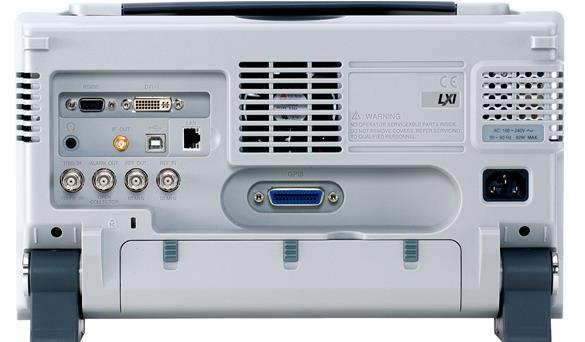
| Back Panel Input/Output | ||
| reference output | ||
| Connector type | BNC Female | |
| output frequency | 10 MHz | indicated value |
| Output Amplitude | 3.3V CMOS | |
| Output Impedance | 50 Ω | |
| reference input | ||
| Connector type | BNC Female | |
| Input Reference Frequency | 10 MHz | |
| Input Amplitude | -5 dBm ~ +10 dBm | |
| Frequency lock range | Within ±5ppm of input reference frequency to | |
| warning output | ||
| Connector type | BNC female chassis connector | Open Collector Control |
| Trigger Input/Gate Scan Input | ||
| Connector type | BNC female chassis connector | |
| Input Amplitude | 3.3V CMOS | |
| switch modes or data streams | automatic switching | |
| LAN (TCP/IP) interface | ||
| Connector type | RJ-45 | |
| (an official) standard | 10Base-T; 100Base-Tx; Auto-MDIX | |
| USB Controlled | ||
| Connector type | B-connector | For remote control only, supports USB TMC |
| communication protocols | Version 2.0 | Supports full/high speed |
| IF output | ||
| Connector type | SMA Female | |
| (electrical) impedance | 50Ω | indicated value |
| midrange frequency | 886 MHz | indicated value |
| output collimation | -25 dBm | 10dB attenuation, RF input: 0dBm @1GHz |
| headphone output | ||
| Connector type | 3.5mm stereo jack, wired mono operation | |
| screen output | ||
| Connector type | DVI-I connector (integrates analog and digital), single link, compatible with VGA or HDMI standards using a converter | |
| RS-232 interface | ||
| Connector type | D-sub 9-pin female | tx,rx,rts,cts |
| GPIB interface (optional) | ||
| Connector type | IEEE-488 Bus Connectors | |
| AC power input | ||
| power supply (of an appliance etc) | AC 100 V ~ 240 V, 50 / 60 Hz automatic gear selection | |
| Battery module (optional) | ||
| battery module | 6 cells, rechargeable lithium battery, 3S2P | Conforms to UN38.3 specifications |
| input voltage | DC 10.8V | |
| quantitative (science) | 5200 mAh / 56Wh | |
| General specifications | ||
| Internal data storage capacity | Built-in 16MB | |
| power consumption | <65 W | |
| Warm-up time | < 30 minutes | |
| temperature range | '+5 °C ~ +45 °C; -20 °C ~ + 70 °C | Operating range; storage range |
| weights | 4.5 kg (9.9 lb) | Includes all options (basic + signal tracker + GPIB interface + battery module) |
| sizes | 210 x 350 x 100 (mm)8.3 x 13.8 x 3.9 (in) | approximate |
| Tracking generator (optional) | ||
| Output frequency range | 100 kHz ~ 3.25 GHz | |
| Output power level range | -50 dBm ~0 dBm, adjustable in 0.5 dB steps | |
| absolute accuracy | ± 0.5 dB | Reference Point: 160MHz, -10dBm, 10dB attenuation, 20~30°C |
| Output flatness | Reference Point 160MHz, -10dBm; 100 kHz ~ 2 GHz; 2 GHz ~ 3.25 GHz | ± 1.5 dB |
| Output level switching inaccuracy | ± 0.8 dB | ± 2 dB |
| harmonic (wave with frequency an integer multiple of the fundamental) | < -30 dBc | Referenced to -10 dBm |
| Reverse Voltage | Maximum +30dBm | Typical, output collimation -10dBm |
| Connector type | N female chassis connector | |
| (electrical) impedance | 50Ω | indicated value |
| Output VSRW | < 1.6:1 | 300 kHz ~3 GHz, input attenuator ≥12 dB |
Optional Information
Opt.01 Tracking Source
Opt.02 Battery modules
Opt.03 GPIB Interface
Optional Accessories
GSC-009 Portable backpack
GRA-415 Rack Panel
Ordering Information
GSP-9330 3.25 GHz Spectrum Analyzer
EMC testing solutions:
GKT-008 EMI Near Field Probe Set
GLN-5040A Linear impedance stabilization network
GIT-5060 Isolation Transformer
GPL-5010 Pulse Limiter
Recommended


