 Comprehensive test and measurement service provider-Shenzhen Weike Electronic Technology Co.
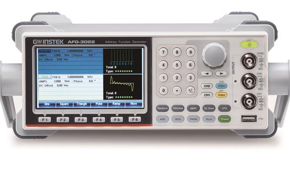
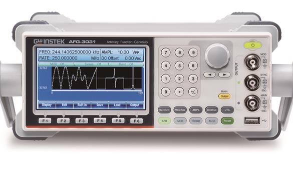
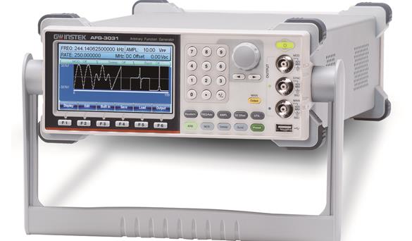
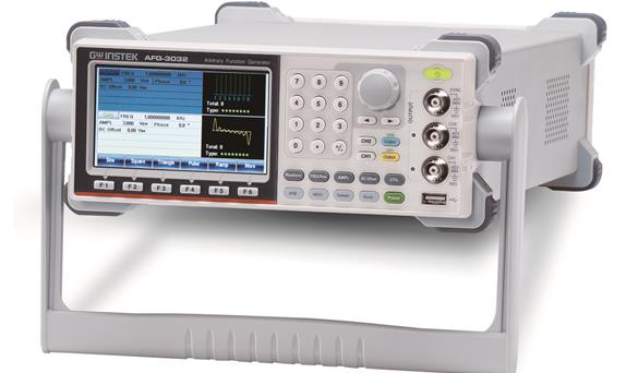
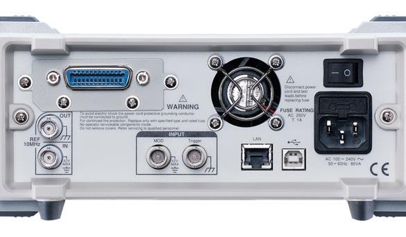
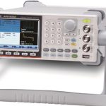


Goodwell introduces the AFG-3000 series of 20MHz/30MHz single-isolated channel and dual-isolated channel arbitrary waveform signal generators for industrial, scientific research and educational applications. In the isolated output design, all output channels are isolated from ground and earth, which is suitable for floating circuit test applications, such as DC and AC outputs up to +42V or -42V when connected in series with DC voltage of a power supply, and the dual channels can be used independently or simultaneously by multiple instruments without the need to consider the problem of ground references, such as engine controllers or transmission devices in automotive electronics. controllers or transmissions in automotive electronics, for example. They offer arbitrary waveform characteristics with 250 MSa/s sampling rate, 16-bit resolution, and 8 M-point memory depth. In addition to generating arbitrary waveforms by downloading pre-edited waveform files into memory, users can also utilize the DSOLink function built into the AFG-3000 series to duplicate the signals measured by the Goodwell digital oscilloscopes.
The AFG-3000 series supports multi-channel synchronized phase operation up to 6 units and 12 channels of phase synchronization. Users can input 10 MHz atomic clock frequency standard through external signal source to improve the accuracy of frequency output. Frequency Sweep and Amplitude Sweep are supported, which can be combined with linear/logarithmic, unidirectional (sawtooth wave)/bidirectional (triangle wave), continuous/single trigger/threshold trigger functions to achieve different sweeps to meet various application requirements. Frequency sweep can test the frequency response of electronic components such as filters and low frequency amplifiers. Amplitude sweeps can simulate vibration testing (in combination with vibration testers), fatigue aging testing of various materials, and linearity testing of low-frequency amplifiers, among others.
AFG-3032 Pulse Generator Function Introductionhttp://v.youku.com/v_show/id_XMTczMDQzMDA4OA==.html?spm=a2hzp.8253869.0.0
AFG-3032 Phase Addition Modulation Function Introductionhttp://v.youku.com/v_show/id_XMTczMDQxNjU0MA==.html?spm=a2hzp.8253869.0.0
AFG-3032 Isolation Channel Function Introductionhttp://v.youku.com/v_show/id_XMTcyMjcyODMyMA==.html?spm=a2hzp.8253869.0.0
AFG-3032 Multi-Channel Synchronized Phase Run Function Introductionhttp://v.youku.com/v_show/id_XMTcyMjQ5NzAxNg==.html?spm=a2hzp.8253869.0.0
AFG-3032 Harmonic Signal Generator Functionhttp://v.youku.com/v_show/id_XMTcyMjM5NDMyMA==.html?spm=a2hzp.8253869.0.0
AFG-3032 Amplitude Scan Function Introductionhttp://v.youku.com/v_show/id_XMTcwMDM5MTQyOA==.html?spm=a2hzp.8253869.0.0
Quick Selection
| model number | frequency range | sampling rate | resolution (of a photo) | Waveform length | channel number |
| AFG-3031 | 1uHz-30MHz | 250MSa/s | 16bits | 8M | 1 |
| AFG-3032 | 1uHz-30MHz | 250MSa/s | 16bits | 8M | 2 |
| AFG-3021 | 1uHz-20MHz | 250MSa/s | 16bits | 8M | 1 |
| AFG-3022 | 1uHz-20MHz | 250MSa/s | 16bits | 8M | 2 |
| Detailed specifications | |||||
| AFG-3031 | AFG-3032 | AFG-3021 | AFG-3022 | ||
| channel number | |||||
| 1 | 2 | 1 | 2 | ||
| specificities | |||||
| Input and output grounding | The ground signals for Channel 1, Channel 2, Sync Output, Modulation Input, Modulation Output and 10 MHz Reference Input are separate and isolated from the instrument case. The withstand voltage between the isolated ground signals and the case is 42 V peak maximum (DC+ AC peak). The other ground signals are connected to the case. | ||||
| Channel 1 and Channel 2 grounding | --- | incommunicado | --- | incommunicado | |
| standard waveform | Sine, Square, Triangle, Ramp, Pulse, Noise, Harmonic, DC | ||||
| arbitrary waveform | |||||
| sampling rate | 250 MSa/s | ||||
| reconstruction rate | 125MHz | ||||
| Memory length | 8M points | ||||
| Amplitude resolution | 16-bit | ||||
| Non-volatile memory | 10 sets of 8M waveforms(1) | ||||
| Definable waveform output | Any 2 to 8M points | ||||
| trig | externally | ||||
| Built-in Function Waveforms | Sinc, exponentially increasing, exponentially decreasing, Gaussian, half-sine, etc. There are 65 types in total | ||||
| frequency characteristic | |||||
| Sine/Square Wave | 1uHz to 30MHz | 1uHz to 20MHz | |||
| pulse wave | 1uHz to 25MHz | 1uHz to 20MHz | |||
| Triangular/Ramped Wave | 1uHz to 1MHz | ||||
| resolution (of a photo) | 1uHz | ||||
| accuracy | degree of stability | ±1 ppm 0 to 50°C; ±0.3 ppm 18 to 28°C | |||
| aging rate | ±1 ppm, per 1 year | ||||
| inaccuracies | ≦ 1 uHz | ||||
| Output Characteristics(2) | |||||
| amplification | realm | 1 mVpp to 10 Vpp (50Ω load); 2 mVpp to 20 Vpp (open circuit) | |||
| accuracy | ±1 mVpp at 1% setting (at 1 kHz, >10 mVpp) | ||||
| resolution (of a photo) | 0.1 mV or 4 digits | ||||
| flatness | 0.1 dB: <10 MHz; 0.2 dB: 10 MHz to 30 MHz (for 1 kHz sine wave with 50Ω load) | ||||
| unit (of measure) | Vpp, Vrms, dBm. | ||||
| bias voltage | realm | ±5 Vpk ac +dc (50Ω load); ±10Vpk ac +dc (open circuit) | |||
| accuracy | 1% Amplitude at setting + 2 mV+ 0.5% | ||||
| waveform output | (electrical) impedance | 50Ω (fixed); > 10MΩ (output off) | |||
| input protection | Short-circuit protection, overload relay automatically disables main outputs | ||||
| Synchronous output | quasi-judicial | TTL compatible >1kΩ | ── | TTL compatible to >1kΩ | ── |
| (electrical) impedance | 50Ω | ||||
| Sine Wave Characteristics | |||||
| Harmonic distortion(5) | -60 dBc DC~1 MHz, Ampl<3 Vpp; -55 dBc DC~1 MHz, Ampl>3 Vpp; -45 dBc 1MHz~5 MHz, Ampl>3 Vpp; -30 dBc 5MHz~30 MHz, Ampl>3 Vpp | ||||
| THD | < 0.2%+0.1mVrms; DC to 20 kHz | ||||
| Parasitic noise (non-harmonic)(5) | -60 dBc DC ~ 1 MHz; -50 dBc 1MHz ~ 20MHz; -50 dBc+ 6 dBc/octave 1MHz ~ 30MHz | ||||
| phase noise | <-110dBc/Hz typical, 15kHz offset, carrier at 10MHz | ||||
| square wave characteristic | |||||
| Rise/fall time | <8 ns (3) | ||||
| Excessive signals | < 5% | ||||
| asymmetry | Cycle of 1% +1 ns | ||||
| periodic ratio | 20.0% to 80.0% , ≦ 25 MHz; 40.0% to 60.0% , 25 to 30 MHz | ||||
| jitter rate | 0.01%+525ps < 2 MHz; 0.1%+75ps > 2 MHz | ||||
| Ramp Characteristics | |||||
| linearity | Peak output < 0.1% | ||||
| symmetry | 0% to 100% (0.1% resolution) | ||||
| Pulse wave characteristics | |||||
| duty cycle | -0.625* [(rise time - 0.6ns) + (fall time - 0.6ns)] | ||||
| cyclicality | Cycle≧Width + 0.625*[(Rise Time - 0.6ns) + (Fall Time - 0.6ns)] | ||||
| Duty Cycle Range | 0.017% to 99.983% | ||||
| Duty Cycle Resolution | 0.00% | ||||
| Pulse width range | 20ns to 999830s | ||||
| Excessive signals | <5% | ||||
| judder | 100 ppm + 50 ps | ||||
| Rise and fall time | 9.32 ns to 799,900s (0.01ns or 3 digits) | ||||
| Harmonic Generator Characteristics | |||||
| harmonic order | ≦8 | ||||
| Harmonic type | Odd, even, all, customized; amplitude and phase of all harmonics can be set | ||||
| AM modulation | |||||
| carrier waveform | Sine, Square, Triangle, Ramp, Pulse, Arbitrary Waves | ||||
| Modulated waveforms | Sine, Square, Triangle, Up/Down Ramp | ||||
| frequency modulation | 2 mHz to 20 kHz | ||||
| peak offset | 0% to 120.0% | ||||
| Signal Source | Internal / External | ||||
| FM modulation | |||||
| carrier waveform | Sine, Square, Triangle, Ramp | ||||
| Modulated waveforms | Sine, Square, Triangle, Up/Down Ramp | ||||
| frequency modulation | 2 mHz to 20 kHz | ||||
| peak offset | DC to 30 MHz (1 uHz resolution) | DC to 20 MHz (1 uHz resolution) | |||
| Signal Source | Internal / External | ||||
| PM modulation | |||||
| carrier waveform | Sine, Triangle, Ramp | ||||
| Modulated waveforms | Sine, Square, Triangle, Up/Down Ramp | ||||
| frequency modulation | 2 mHz to 20 kHz | ||||
| phase shift | 0∘ to 360∘, 0.1∘ resolution | ||||
| Signal Source | inside (part, section) | ||||
| SUM summation modulation | |||||
| carrier waveform | Sine wave, Triangle wave, Ramp wave, Pulse wave, Noise | ||||
| Modulated waveforms | Sine, Square, Triangle, Up/Down Ramp | ||||
| frequency modulation | 2 mHz to 20 kHz | ||||
| proportions | Carrier amplitude from 0% to 100%, 0.01% resolution | ||||
| Signal Source | Internal/external | ||||
| PWM modulation | |||||
| carrier waveform | square wave | ||||
| Modulated waveforms | Sine, Square, Triangle, Up/Down Ramp | ||||
| frequency modulation | 2 mHz to 20 kHz | ||||
| misalignment | Pulse width 0% to 100.0%, 0.1% resolution | ||||
| Signal Source | Internal / External | ||||
| FSK modulation | |||||
| carrier waveform | Sine wave, square wave, triangle wave, ramp wave, pulse wave | ||||
| Modulated waveforms | 50% Square Wave Duty Cycle | ||||
| internal frequency | 2 mHz to 1 MHz | ||||
| frequency range | DC to 30MHz | DC to 20MHz | |||
| Signal Source | Internal / External | ||||
| scan | |||||
| waveform | Sine, Square, Triangle, Ramp | ||||
| pattern | Frequency, Amplitude | ||||
| functionality | Linear or logarithmic | ||||
| orientations | Up or down | ||||
| Start/stop frequency | Any frequency in the range of the waveform | ||||
| scanning time | 1 ms to 500 s (1 ms resolution) | ||||
| Trigger Mode | Single, external, internal | ||||
| Trigger source | Internal/external | ||||
| cluster of hair | |||||
| waveform | Sine, Square, Triangle, Ramp, Pulse, Arbitrary (N-Cycle) | ||||
| frequency | 1 uHz to 30 MHz (4) | 1 uHz to 20MHz (4) | |||
| reckoning | 1 to 1000000 cycles or infinite | ||||
| Start/end phase | -360.0∘ to +360.0∘ (0.1° resolution) | ||||
| internal cycle | 1 us to 500 s | ||||
| Gateway Source | external trigger | ||||
| Trigger source | Single, external or internal rate | ||||
| Trigger delay | N-cycle, infinite: 0us to 100 s (1us resolution) | ||||
| External Modulation Input | |||||
| typology | AM, FM, PWM | ||||
| voltage range | ± 5V full scale | ||||
| Input Impedance | 10kΩ | ||||
| frequency | DC to 20 kHz | ||||
| External Trigger Input | |||||
| pattern | FSK, Cluster, Scanning | ||||
| Input alignment | TTL compatible | ||||
| gradient | Up or down (selectable) | ||||
| pulse width | > 100 ns | ||||
| input rate | DC to 1 MHz | ||||
| Input Impedance | 10kΩ, DC coupling | ||||
| waiting time | Sweep: < 10 us (typical); Cluster: < 100 ns (typical) | ||||
| judder | Sweep: 2.5 us; Cluster: 1 ns; except pulse wave, 300 ps | ||||
| 10MHz Reference Output | |||||
| output voltage | 1 Vp-p/50Ω square wave | ||||
| Output Impedance | 50Ω, AC coupling | ||||
| output frequency | 10MHz | ||||
| 10MHz Reference Input | |||||
| Input Voltage | 0.5 Vp-p to 5 Vp-p | ||||
| Input Impedance | 1kΩ, single-ended, ac-coupled | ||||
| Input frequency | 10MHz ± 0.5% | ||||
| waveform | Sine or square wave (50±5% duty cycle) | ||||
| grounding | 42Vpk max. | ||||
| modulating output | AFG-3031/3021 models only | ||||
| pattern | AM, FM, PM,PWM,SUM,Scanning | ||||
| amplitude range | ≧ 1Vpp | ||||
| (electrical) impedance | > 10kΩ typical | ||||
| external synchronization | |||||
| Phase delay (max) | Series wiring: 39ns + (N-2)*39ns ± 25ns Parallel wiring: (N-1)*6ns ± 25ns (N is the number of connected instruments) | ||||
| Maximum number of connections | Series wiring: 4, Parallel wiring: 6 | ||||
| Applicable functions | Sine, Square, Triangle, Pulse, Ramp, Harmonic, Modulation, Sweep, Cluster | ||||
| Storage/calling | 10 groups of memory space | ||||
| interfaces | GPIB (optional), LAN, USB | ||||
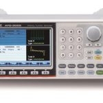
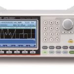
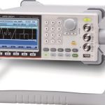
| screen (TV, computer or movie) | 4.3 inch TFT LCD, 480 × 3 (RGB) × 272 | ||||
| General specifications | |||||
| power supply | AC 100~240V , 50~60Hz | ||||
| power consumption | 85 VA | ||||
| operating environment | Compliant Temperature: 18 ~ 28∘C; Operating Temperature : 0 ~ 40∘C; Relative Humidity: ≤ 80%, 0 ~ 40°C; ≤ 70%, 35 ~ 40°C; Safety Class: CAT II | ||||
| Working height | 2000 meters | ||||
| degree of contamination | IEC 61010 Degree 2, indoor use | ||||
| Storage temperature | -10 ~ 70∘C, Humidity: ≤70% | ||||
| Dimensions (WxHxD) | Desktop : 265 (W) x 107 (H) x 374 (D) | ||||
| weights | Approx. 4kg | ||||
| The safety design is in accordance with | EN61010-1 | ||||
| EMC test compliance | en 55011, iec-61326-1 | ||||
| replacement (parts) | Test Lead GTL-110×1 (AFG-3031/AFG-3021),Test Lead GTL-110×2 ( AFG-3032/AFG-3022),User's Manual CD-ROM×1,Simple Manual x1,Power Cord x1 | ||||
| (1). A total of ten waveforms can be stored. (Each waveform can consist of up to 8M points). | |||||
| (2). When operating at temperatures outside the range of 0∘C to 28∘C, the specifications add 1/10th of the output amplitude and offset per degree of ∘C specification (1 year specification). | |||||
| (3). Edge time decreases at higher frequencies. | |||||
| (4). Only "infinite" counting is allowed for sine and square waveforms over 25MHz. | |||||
| (5). Harmonic distortion and parasitic noise are limited to a floor noise of -70 dBm at low amplitudes. | |||||
Standard Accessories
GTL-101, BNC to Alligator Clip Cable *1 (AFG-3031/AFG-3021)
GTL-101, BNC to Alligator Clip Cable *2 (AFG-3022/AFG-3032)
Quick Guide *1, CD-ROM *1 (User's Manual and AFG Software), Power Cord *1
optional
Opt 01, GPIB card
Optional Accessories
GTL-246, USB Type A to Type B cable
Free Download
Arbitrary Waveform Editing Software
Recommended


