 Comprehensive test and measurement service provider-Shenzhen Weike Electronic Technology Co.
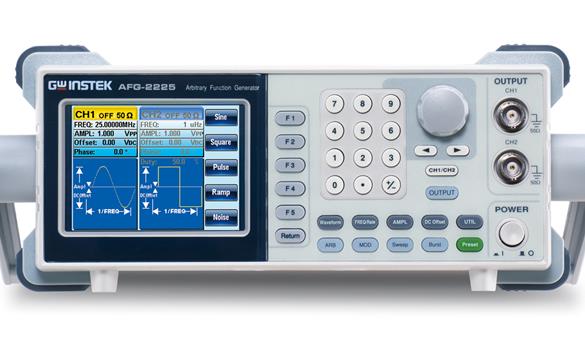
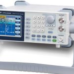


The AFG-2225 is a basic dual-channel arbitrary waveform signal source that offers superior performance in its class. Both channels provide equal characteristics for dual-signal applications such as differential signaling or IQ modulation. Excellent C/P makes the AFG-2225 a practical device for speeding up the development process. Key features of the two channels include 10Vpp output amplitude; 25MHz frequency bandwidth with 1uHz resolution; built-in Sine, Square, Ramp (Triangle), and Noise waveforms. 1%~99% square waveforms with adjustable duty cycle can be used as a pulse signal source. For the arbitrary waveform function, two channels provide 120MSa/s sampling rate, 10-bit resolution, and 4k-point memory depth. Meanwhile, 66 kinds of arbitrary waves are built-in for users to choose according to their needs. In addition, the AFG-2225 provides AM/FM/PM/FSK/SUM modulation, sweep, Burst and frequency counter for various communication applications.
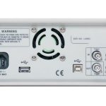
In addition, the fully digital user interface with 3.5-inch color LCD can display all the operation information, including the real output waveform of the current output. In terms of communication interface, AFG-2225 provides USB Host/Device interface. USB Host interface supports connecting with Goodwell GDS series oscilloscopes for direct waveform reconstruction and saving/retrieving data on the flash memory device; USB Device supports remote control and sending waveforms edited on the computer to AFG-2225 through arbitrary waveform editing software.
AFG-2225https://v.youku.com/v_show/id_XNDYyMjExMTY4MA==.html
AFG-2225 Signal Source True Dual Channel Coupling Functionhttp://v.youku.com/v_show/id_XNjg0NjMyNjYw.html?spm=a2hzp.8253869.0.0
AFG-2225 Signal Source Arbitrary Wave Functionhttp://v.youku.com/v_show/id_XNjg0NjM2MDcy.html?spm=a2hzp.8253869.0.0
AFG-2225 Signal Source Tracking and Phase Functionhttp://v.youku.com/v_show/id_XNjg0NjI1ODMy.html?spm=a2hzp.8253869.0.0
AFG-2225 Signal Source Phase Addition Modulation Functionhttp://v.youku.com/v_show/id_XNjg0NjIxNzEy.html?spm=a2hzp.8253869.0.0
| norm | |||
| CH1 | CH2 | ||
| waveform | Sine, Square, Ramp, Pulse, Noise, Arbitrary Waves | ||
| Arbitrary wave function | |||
| sampling rate | 120 MSa/s | ||
| reconstruction rate | 60 MHz | ||
| Waveform length | 4k point | ||
| vertical resolution | 10 bits | ||
| Record length | 4k point | ||
| frequency characteristic | |||
| realm | Sine, Square | 1uHz~25MHz | |
| oblique wave | 1uHz~1MHz | ||
| resolution (of a photo) | 1uHz | ||
| precision | degree of stability | ±20 ppm | |
| aging rate | ±1 ppm/year | ||
| error tolerance | ≤1 mHz | ||
| Output Characteristics | |||
| amplitude | realm | 1mVpp ~ 10 Vpp (with 50Ω load); 2mVpp ~ 20 Vpp (open circuit); 1mVpp ~ 5 Vpp (with 50Ω load) 20MHz ~ 25MHz; 2mVpp ~ 10 Vpp (open circuit) 20MHz ~ 25MHz | |
| precision | ±2% of setpoint ±1 mVpp ( 1 kHz) | ||
| resolution (of a photo) | 1mV or 3 bits | ||
| flatness | ±1% (0.1 dB) ≤100kHz; ±3% (0.3 dB) ≤5MHz; ±5% (0.4 dB) ≤12MHz; ±10% (0.9 dB) ≤25MHz (1kHz sine wave) | ||
| unit (of measure) | Vpp, Vrms, dBm | ||
| DC Offset | realm | ±5 Vpk ac +dc (with 50Ω load); ±10Vpk ac +dc (open circuit); ±2.5 Vpk ac +dc (with 50Ω load) 20MHz ~ 25MHz; ±5Vpk ac +dc (open circuit) 20MHz ~ 25MHz | |
| precision | 2% of setpoint + 10mV + 0.5% of amplitude | ||
| waveform output | (electrical) impedance | 50Ω typical (fixed); > 10MΩ (output off) | |
| safeguard | Short-circuit protection, overload relay automatically prohibits outputs | ||
| Sine Wave Characteristics | |||
| harmonic distortion | ≤ -55 dBc DC ~ 200kHz, Ampl > 0.1Vpp; ≤ -50 dBc 200kHz ~ 1MHz, Ampl > 0.1Vpp; ≤ -35 dBc 1MHz ~ 5MHz, Ampl > 0.1Vpp; ≤ -30 dBc 5MHz ~ 25MHz, Ampl > 0.1Vpp | ||
| square wave characteristic | |||
| Rise/fall time | ≤25ns at maximum output (with 50 Ω load) | ||
| Excessive signals | 5% | ||
| asymmetry | Cycle of 1% +5 ns | ||
| Adjustable Duty Cycle | 1.0% ~ 99.0% ≤ 100kHz; 10% ~ 90% ≤ 1MHz; 50% ≤ 25MHz | ||
| Ramp Characteristics | |||
| linearity | < 0.1% of peak output | ||
| Adjustable symmetry | 0% ~ 100% (0.1% resolution) | ||
| Pulse wave characteristics | |||
| cyclicality | 40ns~2000s | ||
| pulse width | 20ns~1999.9s | ||
| Excessive signals | <5% | ||
| jitter rate | 20ppm +10ns | ||
| AM modulation | |||
| carrier wave | Sine, Square, Ramp, Pulse, Arbitrary Waveforms | Sine, Square, Ramp, Pulse, Arbitrary Waveforms | |
| modulated wave (elec.) | Sine, Square, Triangle, Upslope, Downslope | Sine, Square, Triangle, Upslope, Downslope | |
| modulation frequency | 2mHz ~ to 20kHz (internal); DC ~ 20kHz (external) | 2mHz ~ to 20kHz (internal) DC ~ to 20kHz (external) | |
| modulation depth | 0% ~ to 120.0% | 0% ~ to 120.0% | |
| modulation source | Internal / External | Internal / External | |
| FM modulation | |||
| carrier wave | Sine, Square, Ramp | Sine, Square, Ramp | |
| modulated wave (elec.) | Sine, Square, Triangle, Upslope, Downslope | Sine, Square, Triangle, Upslope, Downslope | |
| modulation frequency | 2mHz ~ 20kHz (internal); DC ~ 20kHz (external) | 2mHz ~ 20kHz (internal); DC ~ 20kHz (external) | |
| peak frequency offset | DC ~ Maximum Frequency | DC ~ Maximum Frequency | |
| modulation source | Internal/external | Internal/external | |
| sweep | |||
| waveform | Sine, Square, Ramp | Sine, Square, Ramp | |
| typology | Linear or logarithmic | Linear or logarithmic | |
| Start/Stop Frequency | 1uHz ~ Maximum Frequency | 1uHz ~ Maximum Frequency | |
| sweep time | 1ms ~ 500s | 1ms ~ 500s | |
| frequency sweep source | Internal/external/manual | Internal / External / Manual | |
| FSK | |||
| carrier wave | Sine, Square, Ramp, Pulse | Sine, Square, Ramp, Pulse | |
| modulated wave (elec.) | 50% Square Wave Duty Cycle | 50% Square Wave Duty Cycle | |
| modulation speed | 2mHz ~ 100 kHz (internal); DC ~ 100 kHz (external) | 2mHz ~ 100 kHz (internal) DC ~ 100 kHz (external) | |
| frequency range | 1uHz ~ Maximum Frequency | 1uHz ~ Maximum Frequency | |
| modulation source | Internal / External | Internal / External | |
| PM | |||
| carrier wave | Sine, Square, Ramp | Sine, Square, Ramp | |
| modulated wave (elec.) | Sine, Square, Triangle, Upslope, Downslope | Sine, Square, Triangle, Upslope, Downslope | |
| modulation frequency | 2mHz ~ 20kHz (internal); DC ~ 20kHz (external) | 2mHz ~ 20kHz (internal); DC ~ 20kHz (external) | |
| phase shift | 0˚ ~ 360˚ | 0˚ ~ 360˚ | |
| modulation source | Internal/external | Internal / External | |
| SUM | |||
| carrier wave | Sine, Square, Ramp, Pulse, Noise | Sine, Square, Ramp, Pulse, Noise | |
| modulated wave (elec.) | Sine, Square, Triangle, Upslope, Downslope | Sine, Square, Triangle, Upslope, Downslope | |
| modulation frequency | 2mHz ~ 20kHz (internal); DC ~ 20kHz (external) | 2mHz ~ 20kHz (internal); DC ~ 20kHz (external) | |
| SUM Depth | 0% ~ 100.0% | 0% ~ 100.0% | |
| modulation source | Internal/external | Internal / External | |
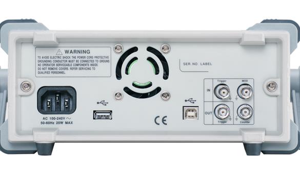
| External Trigger Input | |||
| typology | For FSK, Burst, Sweep | ||
| Input level | TTL compatible | ||
| fringe | Up or down (optional) | ||
| pulse width | >100ns | ||
| Input Impedance | 10kΩ, DC Coupling | ||
| External Modulation Input | |||
| typology | For AM, FM, PM, SUM | ||
| voltage range | ±5V full scale | ||
| Input Impedance | 10kΩ | ||
| frequency | DC ~ 20kHz | ||
| trigger output | |||
| typology | For Burst, Sweep, Arb | ||
| power level (elec.) | TTL compatible 50Ω | ||
| pulse width | >450ns | ||
| maximum speed | 1MHz | ||
| fan out (i.e. number of fans) | ≥4 TTL Load | ||
| I impedance | 50Ω Typical | ||
| dual-channel function | |||
| phase (waves) | '-180˚ ~180˚ synchronized phase | -180˚ ~ 180˚ | |
| haunt | CH2=CH1 | CH1=CH2 | |
| be coupled (with sth) | Frequency (ratio or difference) amplitude & DC offset | Frequency (ratio or difference) | |
| DSO connection | √ | √ | |
| Burst | |||
| waveform | Sine wave, Square wave, Ramp wave | Sine wave, Square wave, Ramp wave | |
| frequency | 1uHz~25MHz | 1uHz~25MHz | |
| Burst Count | 1 ~ 65535 cycles or unlimited | 1 ~ 65535 cycles or unlimited | |
| Start/stop phase | -360 ~ +360 | -360 ~ +360 | |
| internal cycle | 1ms ~ 500s | 1ms ~ 500s | |
| gating source | external trigger | external trigger | |
| trigger source | Single, external or internal rate | Single, external or internal rate | |
| N-Cycle, Unlimited | 0s ~ 655350ns | 0s ~ 655350ns | |
| frequency counter | |||
| realm | 5Hz ~ 150MHz | ||
| precision | Time base accuracy ±1count | ||
| time base | ±20ppm (23˚C ±5˚C) after 30 minutes of warm-up | ||
| resolution (of a photo) | Maximum resolution is 100nHz for 1Hz, 0.1Hz for 100MHz. | ||
| Input Impedance | 1kΩ/1pf | ||
| (level of) sensitivity | 35mVrms ~ 30Vms (5Hz ~ 150MHz) | ||
| Save/Recall | |||
| 10 sets of settings storage | |||
| connector | |||
| USB (Host & Device) | |||
| demonstrate | |||
| 3.5" TFT LCD | |||
| General specifications | |||
| power supply | AC100~240V, 50~60Hz | ||
| power wastage | 25 W (max) | ||
| operating environment | This manual specification Temperature Range: 18 ~ 28˚C Operating Temperature :0 ~ 40˚C Relative Humidity: < 80%, 0 ~ 40˚C Installation Category: CAT II | ||
| Operating altitude | 2000 meters | ||
| Storage temperature | -10~70˚C, Humidity: ≤70% | ||
| Dimensions (WxHxD) | 266(W) x 107(H) x 293(D) mm | ||
| weights | Approx. 2.5kg | ||
| attachment (email) | GTL-101 × 2; Quick Start Guide × 1; CD (User's Manual + Software) × 1; Power Cord × 1 | ||
standard equipment
Quick Start Manual *1
User's Manual CD *1
GTL-101 Test Leads*2
Power cord *1
optional
GTL-110 BNC(M)-BNC(M) RF Cable
Ordering Information
AFG-2225, 25MHz Dual Channel Arbitrary Waveform Signal Generator
standard equipment
Quick Start Manual *1
User's Manual CD *1
GTL-101 Test Leads*2
Power cord *1
optional
GTL-110 BNC(M)-BNC(M) RF Cable
Free Download
Arbitrary waveform editing software
Recommended


AFG2021 Arbitrary Function Generator
Original price was: ¥18,640.00.¥12,862.00Current price is: ¥12,862.00.

