 Comprehensive test and measurement service provider-Shenzhen Weike Electronic Technology Co.
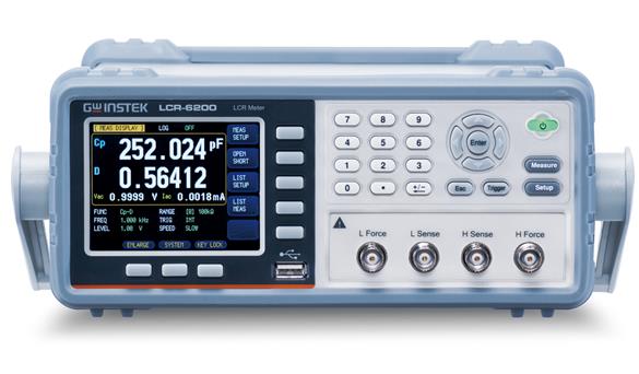


LCR tester can accurately and stably determine a wide range of component parameters, mainly used to test inductance, capacitance, resistance tester. It is characterized by direct function and easy operation. The following is an introduction to simple component parameters:
Resistance R: indicatesoptoelectronicsrightampsThe magnitude of the hindering effect inohm (loanword), symbolized by Ω.
Inductance L: When current passes through the coil, it forms amagnetic fieldsInduction, the induced magnetic field, in turn, produces an induced current to counteract the current through the coil, in Henrys, symbol H.
Capacitance C: is the amount of free charge stored at a given potential difference, the international unit is the farad and the symbol is F.
Reactance X: similar to DCcircuitscenterresistiverightampsThe hindering effect of theAC circuit(e.g.in series connection (electricity)RLC circuit) incapacitorsup toinductorsIt also acts as an impediment to the current in units ofohm (loanword), symbolized by Ω.
Impedance Z: In the presence of resistive, inductive andcapacitorsof a circuit, the obstruction to the current in the circuit is called impedance. Impedance is often expressed as Z, a complex number with the real part called theresistiveThe imaginary part is called reactance.
Conductance G: Conductance is a physical quantity that describes the electrical conductivity of a conductor and is numerically equal to the reciprocal of resistance. The unit is Siemens, symbol S.
DENA B: is pluralguideThe imaginary part of the number, by nature, can be divided into accommodating andexpress gratitude (esp. in writing). The unit isSiemens (company name)The symbol is S
Conductance Y: The reciprocal of impedance Z (complex) is defined as the conductance (complex). The units areSiemens (company name)The symbol is S
Quality factor Q: For electronic resonance systems, theQ-factorIndicates the effect of resistance, individual storage elements ofQ-factorsum of its partssignal frequencyrelated, it is generally the circuit'sresonant frequencyQ = Xs/Rs.
Loss factor D: the reciprocal of Q.
LCR tester is generally used to test inductance and capacitance. The measurement steps are as follows:
1. Setting the test frequency
2. Test voltage or current level
3. Select test parameters, such as Z, Q, LS (series inductance), LP (parallel inductance), CS (series capacitance), CP (parallel capacitance), D, etc.
4. Instrument calibration, calibration of the main open-circuit, short-circuit calibration, high-grade instrument to load calibration
5. Selection of test fixtures
6. Fixture Compensation
7. Place the DUT on the fixture and start testing.
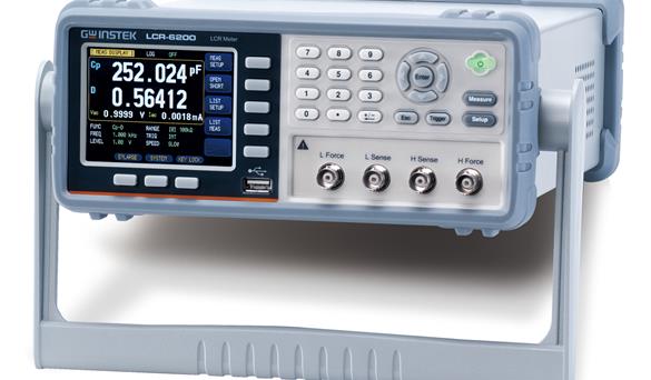
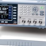
Goodwell Electronics introduces a new series of high precision LCR meters - LCR-6000 series, which offers 5 models with test frequencies from 2kHz ~ 300kHz. The miniaturization of the overall design is one of the features of this series (2U), 1/2 Rack, whether it is placed on the desktop or rack-mounted in the system. Although the LCR-6000 series has been miniaturized, it offers a wide variety of features that can be widely used in all phases of passive component testing, such as R&D, production testing, incoming inspection, etc.
Although the LCR-6000 series has been fully miniaturized, the functions it provides are even more abundant and diverse. First of all, the entire series adopts a 3.5-inch color LCD display, which not only maintains the same richness of display parameters as before ~ displaying the setting conditions and measurement results at the same time, but also adds two additional monitoring parameters; in short, up to four parameter results can be displayed under the same screen, which greatly enhances the effectiveness of measurement. In addition, the addition of large value display mode switching not only emphasizes the measurement results, but also provides PASS/FAIL judgment in this mode, making the judgment of the test faster and more convenient.
Another feature of this series of products is that it is more convenient to use, the LCR-6000 series provides two ways to perform zeroing ~ full band or single point; after the user performs full band zeroing, without turning off the power and changing the test fixtures, the user can change the frequency points within the applicable frequency range to measure, saving time wasted due to the repetitive performance of zeroing; moreover, the frequency within the range is continuous, allowing the user to enter the actual demanded frequency value to test the component. In addition, the frequency within the range is continuous, so the user can enter the actual required frequency value to test the component.
The LCR-6000 series also provides a variety of auxiliary measurement modes to meet the needs of different types of materials in measurement applications. For example, the LCR-6000 series provides an automatic alignment control (ALC) function for the measurement of multilayer ceramic capacitors (MLCCs), which requires test voltage. For inductive components, we provide a test current setting, DC resistance measurement function, and an optional external bias box (±2.5A) to meet the measurement needs. For DC bias testing of capacitive components, an internal ±2.5V adjustable voltage or an optional external bias box (±45V) is provided to allow users to perform material verification measurements. In addition, a 10-step list test function allows the parameters of each test step to be set according to the user's needs in order to observe the trend of the characteristics of the component to be tested.
The LCR-6000 series provides 10 sets of internal memory for easy recall of test conditions, and can store up to 10,000 measurement results for real-time recording of measurement results. At the same time, the LCR-6000 series also provides a USB host that allows the internal storage of results to be retrieved without connecting to a PC, and when the USB host is plugged into a USB flash drive, it can also capture and store the display screen, making it easy for users to create a setup guidebook.
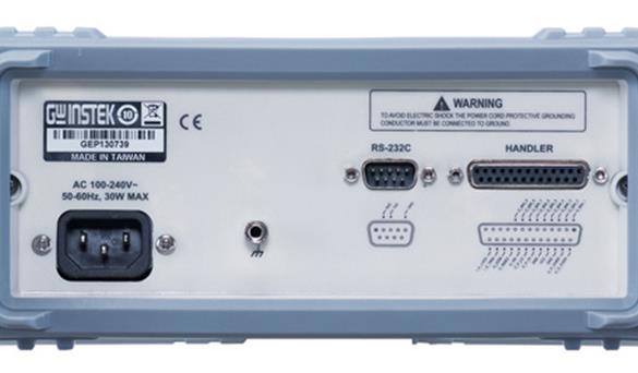
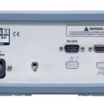
In terms of connecting to external controls, the LCR-6000 series provides a Handler interface, which, together with its own measurement sorting function (9BIN, AUX:1BIN), can be used to connect to a sorter for material sorting operations. For users who need to control and capture measurement results remotely, the LCR-6000 series provides RS-232C, which allows setting control or reading of measurement results to be carried out by transmitting commands through a PC; in addition, the free PC software not only provides users with a tool for storing measurement results immediately, but also saves the time of program development.
The miniaturization of the new LCR-6000 series can effectively improve the limitation of insufficient space for placement; and the diversified measurement functions and display presentation methods are believed to be useful for the evaluation of component adoption in R&D or engineering units, or the demand of component production for its grade sorting, or the confirmation of component specifications in incoming material inspection.
LCR-6000 Series Panel Introduction1https://v.youku.com/v_show/id_XNDYyMjAzMDYwNA==.html
LCR-6000 Zeroing and Function Selection Frequency Setting Videohttps://v.youku.com/v_show/id_XNDYyMjAzMDE0NA==.html
LCR-6000 Series Panel Introduction 2https://v.youku.com/v_show/id_XNDYyMjAzMjY3Mg==.html
Quick Selection
| model number | Test Frequency | Basic precision | 10 Steps to Test Functionality | USB storage function | Standard Interface |
| LCR-6300 | 10Hz-300KHz | 0.05% | YES | YES | USB/RS-232 |
| LCR-6200 | 10Hz-200KHz | 0.05% | YES | YES | USB/RS-232 |
| LCR-6100 | 10Hz-100KHz | 0.05% | YES | YES | USB/RS-232 |
| LCR-6020 | 10Hz-20KHz | 0.05% | YES | YES | USB/RS-232 |
| LCR-6002 | 10Hz-2KHz | 0.05% | YES | YES | USB/RS-232 |
| Detailed specifications | |
| Test Frequency | |
| LCR-6300 | 10Hz to 300kHz (±0.01%) (4-digit display) |
| LCR-6200 | 10Hz to 200kHz (±0.01%) (4-digit display) |
| LCR-6100 | 10Hz to 100kHz (±0.01%) (4-digit display) |
| LCR-6020 | 10Hz to 20kHz (±0.01%) (4-digit display) |
| LCR-6002 | 10Hz to 2kHz (±0.01%) (4-digit display) |
| Output Impedance | |
| 30Ω / 50Ω / 100Ω selectable | |
| Fundamental Accuracy | |
| Slow / Medium | 0.05% |
| speedy | 0.10% |
| test speed | |
| Fast: 25ms / Medium: 100ms / Slow: 333ms | |
| Test signal alignment | |
| input voltage | 10.00mV- 2.00V (±10%) CV:10.00mV- 2.00V (±6%) |
| amps | 100.0uA- 20.00mA (±10%) CC:100.0uA- 20.00mA (±6%) (@2VMax) |
| DC Bias | |
| inside (part, section) | ±2.5V (0.5%+0.005V) |
| Display range | |
| R, X, |Z| | 0.00001Ω ~ 99.9999MΩ |
| G, B, |Y| | 0.01nS ~ 999.999S |
| L | 0.00001uH ~ 9999.99H |
| C | 0.00001pF ~ 9999.99mF |
| D | 0.00001 ~ 9.99999 |
| Q | 0.00001 ~ 99999.9 |
| θd | -179.999° ~ 179.999° |
| θr | -3.14159 ~ 3.14159 |
| DCR | 0.00001Ω ~ 99.9999MΩ |
| Δ% | -99999% ~ 99999% |
| test parameter | |
| Test combinations | Cs-Rs, Cs-D, Cp-Rp, Cp-D, Lp-Rp, Lp-Q, Ls-Rs, Ls-Q,Rs-Q, Rp-Q, R-X, DCR, Z-θr, Z-θd, Z-D, Z-Q, Auto LCZ |
| Monitoring parameters (up to 2 selectable/each time) | Z, D, Q, Vac, Iac, Δ, Δ%, θr, θd, R, X, G, B, Y |
| Tabular testing | |
| 10 steps | |
| sorting | |
| Comparator (9BIN,AUX:1BIN) | |
| memory bank | |
| Internal - Panel Setting | 10 file names |
| Internal - Measurement Data | 10000 Data(.csv) |
| USB storage | 10 file names, 9999 Data files, 999 LCD screen files |
| Other Functions | |
| Automatic Alignment Control (ALC) | ON/OFF |
| on average | 1~256 times |
| trig | Internal / Manual / External / Bus |
| Trigger delay | 0ms~60s |
| judgment function | PASS / FAIL |
| Screen Storage | Direct deposit to USB (Bmp format) |
| monitor | |
| 3.5-inch LCD, RGB color (320x240) | |
| interfaces | |
| RS-232(SCPI), Handler, USB Host | |
| Using the power supply | |
| AC 90V-250V, 50-60Hz, Max. 30VA | |
| Size and Weight | |
| 265(W)x107(H)x312(L) mm, approx. 3 kg | |
Standard Accessories
Safety Guide x 1, Power Cord x 1, Test Cord LCR-06B x 1,
CD-ROM x1 (electronic file of the complete instruction manual)
Optional Accessories
LCR-05 Test Fixture - For Horizontal or Vertical Leg Assemblies
LCR-06B Test Fixture - Kelvin Clips
LCR-07 Test Fixture - Alligator Clips
LCR-08 Test Fixture - Tweezer Format
LCR-15 Test Fixture - For SMD Assemblies (0201 to 1812)
LCR-16 External Bias Box - ±45V
LCR-17 External Bias Box - ±2.5A
GTL-232 RS-232C Connection Cable, 9-pin to 9-pin female chassis connector, 2-3 pairs of jumpers, approx. 2 meters
Ordering Information
LCR-6300 10Hz ~ 300kHz High Precision LCR Meter
LCR-6200 10Hz ~ 200kHz High Precision LCR Meter
LCR-6100 10Hz ~ 100kHz High Precision LCR Meter
LCR-6020 10Hz ~ 20kHz High Precision LCR Meter
LCR-6002 10Hz ~ 2kHz High Precision LCR Meter
Recommended


