 Comprehensive test and measurement service provider-Shenzhen Weike Electronic Technology Co.
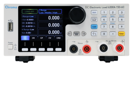


Programmable DC Electronic Load
Programmable DC Electronic Load

63000 series DC electronic load, mainly switching power supply, A/D power supply, power electronic components, adapters, 3C batteries, chargers and some power electronic components and other products test use. With a maximum power rating of 350W, it is suitable for testing a variety of low-power power supply products.
With an operating voltage of 150V, a power range of 250W and 350W, and a maximum current of 60A from a single unit, the 63000 series is a small, lightweight, and mobile electronic load suitable for R&D and validation units.
All models in the series are equipped with a unique User Defined Waveform (UDW), which simulates real current waveforms to meet the needs of power supply testing. In addition, 100 sets of storage function is provided, and the user can call the stored settings at any time. In automated testing, this storage and call function can shorten testing time. In terms of measurement, the 63000 series also provides highly accurate measurement functions, real-time and accurate voltage and current measurement, with three levels for each model. In addition, short-circuit test is one of the necessary test items for power supply testing, and the short-circuit simulation function provided by the 63000 series can effectively solve the needs of power supply testing and automation testing applications.
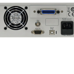
Through the front panel LCD display and knob, you can do simple operation and setting on the 63000 series electronic loads, and also through Ethernet, USB and GPIB interfaces for remote wired or wireless control.
The built-in PWM fan speed control reduces fan noise, and the 63000 series also features over-current, over-power, and over-temperature protections, as well as over-voltage and positive/negative reverse alarms, which greatly enhance product reliability and are reliable products for engineering testing and automated test system integration.
Base load applications
Constant current mode |
Constant Resistance Mode |
Constant Voltage Mode |
Constant Power Mode |
dynamic load

- Dynamic load programmable parameters: current high/low collimation, T1/T2, rate of climb/fall and number of executions
- Setting range for the number of executions 1 ~ 65,535
- Minimum response time of 20μs for 150V models with current creep.
- Ideal for applications that test D/D converter testing
- When the single pulse current load is set to be executed once, a single pulse current pull can be performed, which is suitable for testing the battery's instantaneous high current tolerance level.
 Dynamic changes up to 25kHz |
 One Shot Pulse Current |
Constant polarity mode (CZ Mode)
 |
To avoid instantaneous charging of the capacitors of the motherboard when the switching power supply is energized, which may result in inrush currents that trigger the over-current protection mechanism of the power supply and prevent it from starting up smoothly, the power supply needs to be tested for capacitive loads, and the 63000 series provides a constant impedance load mode for this test. The constant impedance mode simulates the actual inductive reactance, inductance, capacitive reactance and load to carry out load pulling current closer to the real situation. |
Highly Accurate Indicator Measures Three Grades
|
 |
User-defined waveform function (UDW)
The traditional way of pulling an arbitrary current waveform requires a DAQ card or an arbitrary waveform generator to send the current waveform to the electronic load for pulling; the innovative user-customized waveform method is to store the current waveform in the internal flash memory (Flash), which can store 10 groups of current waveforms, up to a maximum of 1.5 million waveform points, and provide the maximum voltage and voltage values occurring in the course of the pulling process at the same time of pulling actual current. The actual current is pulled and the positive and negative values of the maximum voltage occurring during the pulling process are also provided, which greatly saves the time of using an oscilloscope to confirm the voltage peaks.

Battery Discharge Test
- Three discharge modes: constant current, constant resistance and constant power mode
- Setting the cut-off voltage and stopping time (1 sec~100,000 sec) allows the electronic load to stop pulling correctly and ensures that the battery will not be damaged due to over-discharge.
- Measurement of battery discharge capacity (WH, AH) and total discharge time
- Can also be used for ultra-capacitor discharge time testing and other similar applications.

▲ Calculate battery discharge (WH & AH)
Minimum Load Timing Function
Simulates a variety of different real-life pull-load conditions with a minimum timing time of 100 μs. The following are generally common programming timing applications.
|
 ▲ 100 group timing |
Customized shortcut design
 |
|
Overcurrent and overpower testing
|
 |
graphical operating software
Friendly graphical operation software interface, including all operating functions, so that users can easily get started, easy to operate. 63000 series of standard USB communication interface can be another two optional purchase of GPIB or Ethernet card, a variety of communication interfaces, so that users have a more flexible choice.
| model number | relate (a story or information) |
| 63000 Series | Programmable DC Electronic Load |
| 63003-150-40 | Programmable DC Electronic Load 150V / 40A / 250W |
| 63004-150-60 | Programmable DC Electronic Load 150V / 60A / 350W |
| A600009 | GPIB cable (200cm) |
| A600010 | GPIB cable (60cm) |
| A630000 | 63000 Series PC Graphical Software Operation Interface |
| A636000 | GPIB interface |
| A636010 | Ethernet interface |


