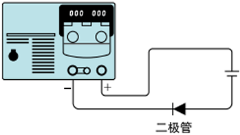
When a load that accumulates energy, such as a battery, is connected to the output of the PAN-A Series, a large current flows from the load to the internal capacitor through the protection diode of the internal output control circuit, which may cause internal damage and reduce the life of the load. In this case, connect a diode in series between the main body of the power supply and the load to prevent reverse current.
one's special ability or strong points
safety function
Overvoltage protection devices (OVP)
When overvoltage occurs due to misoperation or accident, the power switch is cut off instantaneously (within 50ms of operation time) with a circuit protector to protect the load (175W type and 350W type (TYPE0, 12) cut off the rectifier circuit by the gate block method). In particular, the OVP of this series is a preset type, so by pressing the preset button, you can check the operating voltage while looking at the voltmeter from the panel, and the OVP can be operated without interrupting the operation of the OVP during the aging process.
Overheating protection circuit
The power switch is cut off when the temperature of the main parts inside the machine exceeds the specified value. Moreover, a thermal fuse is built into the main transformer or sub-transformer to provide further safety.
Voltage Detection Circuit
When the voltage of the electrolytic capacitor for filtering exceeds the rated voltage due to incorrect operation of the remote switching switch inside the panel or a fault in the rectifier circuit, the rectifier circuit is cut off momentarily.
surge absorber
Protects the mainframe from surge voltages generated by power lines such as lightning.
Preventing Reverse Connection Circuits
The unit will initiate self-protection even if a reverse polarity voltage is applied to the output.
Overcurrent detection circuit
The output current is often monitored by a comparative increaser to prevent excessive inputs from exceeding the rated value during remote control, and to protect the machine from overcurrents caused by incorrect operation of the remote toggle switch in the panel.
additional information
The PAN-A series has a wide range of applications and can be used with a variety of loads. If you use the PAN-A Series in a way that is consistent with the load, it may cause a malfunction or incorrect operation, so it is necessary to take the necessary countermeasures.
Batteries and high-power loads are loads that accumulate energy.
When the load current has a peak value or is pulsed.
In digital circuits or motor drive circuits, the load current waveform in the meter indication (average value) clock even if it is within the rated value, when the peak value exceeds the rated value, it instantly enters the field of steady current, and therefore the output voltage decreases and the voltage becomes unstable. The basic countermeasure is to increase the output current (increase the current setting value or current capacity), but when the pulse amplitude is narrow or the peak value is small, the method of installing a high-power capacitor at the load side is sometimes effective.

inductive load
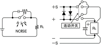
- The reverse electromotive force caused by switching the power supply on and off or by changes in the voltage setting is shunted by the protection diode D1, which is connected in parallel with the output, and does not damage the power supply.
- If pulsating noise generated by an inductive load is applied with the same polarity as the power supply, protect the power supply by connecting diode D2 in series and inserting a CR absorber for noise prevention at both ends of the switch.

When the output is turned on and off by mechanical switching
- When switching a DC output of 100V or more through a switch, the contacts of the switch are significantly depleted due to arc discharge, etc., and noise is generated. This noise sometimes enters the error increaser of the power supply through the load line, making the output unstable. As in the case of inductive loads, please take the same treatment as in the case of inductive loads, and connect a CR absorber in the vicinity of the contact point to implement noise countermeasures.
- Please switch on and off the sensing line at the same time when sensing remotely.
About the sudden current
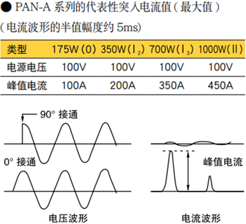
When the power supply is turned on, an inrush current is generated when the power is turned on. This inrush current, also known as inrush current, is theoretically not generated as an excessive phenomenon when the power switch is turned on near the phase angle of 90° (π/2) of the voltage waveform due to the magnetic saturation of the transformer core, but when the power switch is turned on at a phase angle of 0° (past zero), the Max current, shown in the table, will be generated. In fact, the hysteresis characteristics of the B-H curve of the core material, or the different directions of the residual magnetic beam due to the timing of cutting off the switch, or the impedance of the linked AC line can cause the sudden entry current to be out of synchronization. In systems using multiple PAN-A series, pay attention to the capacity of the AC power supply or distribution panel when the power is turned on at the same time.
About negative voltage
When the OUTPUT switch is turned off and the current setting knob is turned fully counterclockwise, a negative voltage of about 0.6V is generated at the output section. As a result of this voltage, a reverse current of about 10mA flows to the load. Therefore, this series may not be suitable for loads where this current causes problems.
About the front output terminals
The front output terminal is a subsidized output terminal. When using this terminal, it may not be possible to meet the specifications. Also, for models with rated output voltage of 60V or more, use the supplied terminal cover.
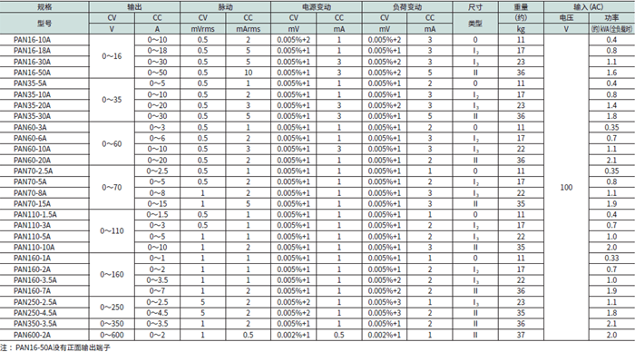
※This terminal is not equipped in PAN16-50A.
Wiring for output
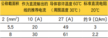
Relationship between cross-sectional area and current capacity and resistance of wiring material.
Product Lineup
 Comprehensive test and measurement service provider-Shenzhen Weike Electronic Technology Co.


